106 Rockwell Automation Publication 750-IN100B-EN-P - July 2017
Chapter 5 Power Wiring
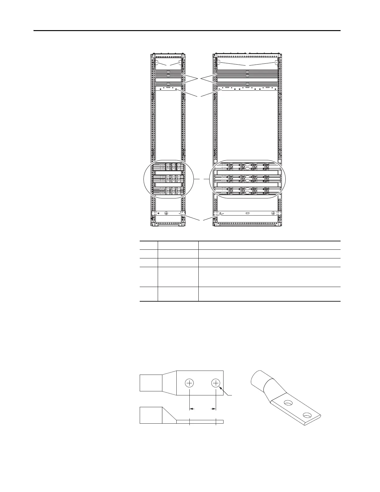
Figure 56 - Optional Entry and Exit Wire Bays
Field Connections
AC line input power and output motor connections are made by using
customer-supplied two-hole standard barrel lugs that are either crimp or
mechanical type. Barrel lugs that are used to make the power cable connections
to bus bars must have the dimensions in the following graphic.
Figure 57 - UL-Listed Barrel Lug Dimensions
Use the vendor-recommended tooling to fasten crimp type terminals to
cabling. Torque mechanical type terminals according to vendor instructions.
Item Name Description
1 DC bus DC power supply
2 Control bus Control power supply
3 Power bus R/L1, S/L2, T/L3 AC line input power connections (entry wire bay)
or
U/T1, V/T2, W/T3 motor connections (exit wire bay)
4 PE grounding bar Terminating point to chassis ground for incoming AC line and motor shield.
PE ground bar clamps, kit number SK-RM-GRNDCLMP-nn, are available.
400 mm (15.7 in.) 800 mm (31.5 in.)
44.5 mm
(1.75 in.)
Ø 12.7 mm
(0.5 in.)

 Loading...


