Rockwell Automation Publication 750-IN100B-EN-P - July 2017 79
Mechanical and Electrical Installation Chapter 4
Remove LCL Filter Module
Follow these steps to remove the LCL filter module from an enclosure.
Power Module Connections
If power modules have already been removed, skip this section and go to LCL
Module Connections on page 81.
1. Review the General Precautions on page 7
.
2. Open the enclosure door.
3. If present, remove the protective guards from the enclosure. See Remove
Protective Guards on page 70
.
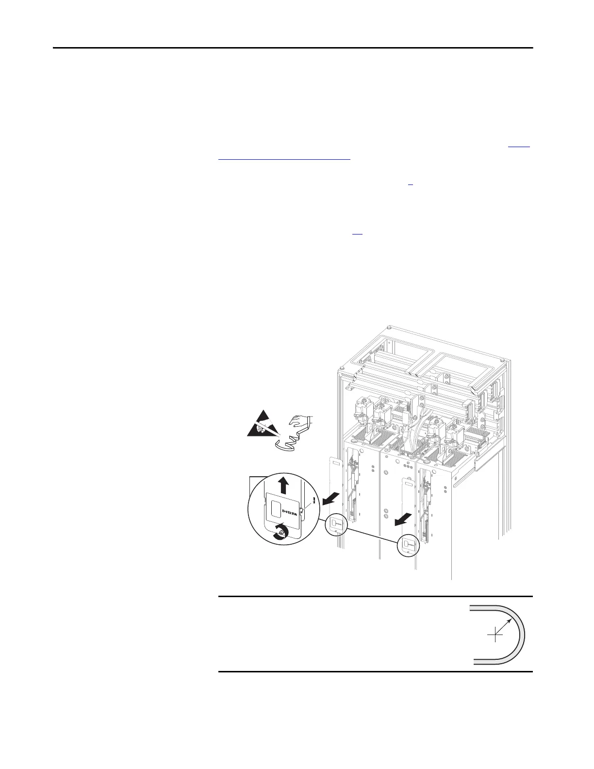
4. Loosen the screw that secures the connections cover to the front of the
adjoining power module(s).
5. Use the screw to lift the connections cover up and off of the power
module chassis.
Figure 41 - Power Module Connections Covers
IMPORTANT
Minimum inside bend radius for fiber-optic cable is
50 mm (2 in.). Any bends with a shorter inside radius
can permanently damage the fiber-optic cable. Signal
attenuation increases as inside bend radius is
decreased.

 Loading...


