Rockwell Automation Publication 750-IN100B-EN-P - July 2017 169
I/O Wiring Chapter 6
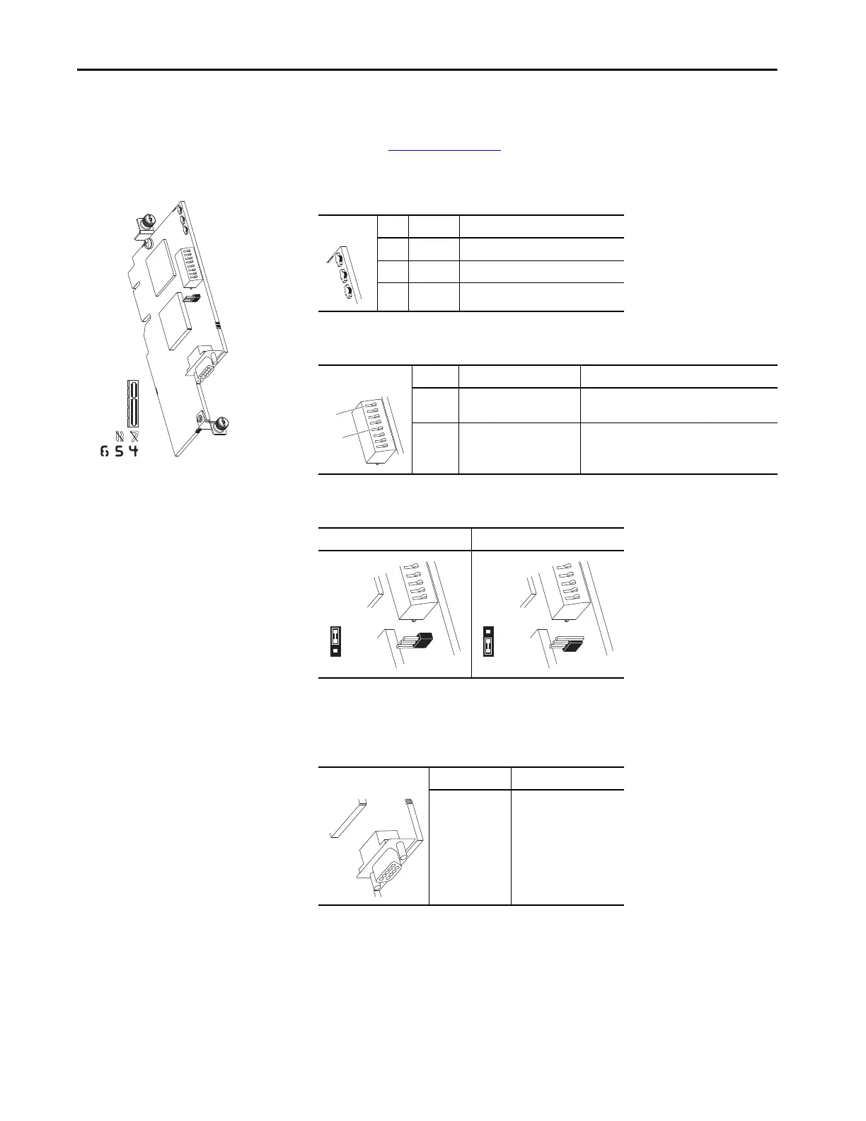
Profibus Option Module
For complete information on the Profibus Option Module, refer to the
PowerFlex 20-750-PBUS Profibus DPV1 Option Module User Manual,
publication 750COM-UM004
.
20-750-PBUS
Table 50 - Profibus Option Module LED Indication
LED Name Description
1 PORT DPI Connection Status
2 MOD Option Module Status
3 NET A ControlNet Channel A Status
Table 51 - Profibus Option Module Node Address Switches
Switch Name Description
1 Endianness Selection Switch
(Switch 8)
Sets endianness of data transmitted over
network.
2 Node Address Switches
(Switches 1…7)
Sets the node address of the option module.
Table 52 - Profibus Option Module Selection Jumper
Profibus Mode Profidrive Mode
(1)
(1) Profidrive Mode is not yet supported. Changing the jumper position has no effect.
Profibus is selected in both positions.
Table 53 - Network Connector
Name Description
Profibus DB9
Female Connector
Profibus connection to the
network.
3

 Loading...


