144 Rockwell Automation Publication 750-IN100B-EN-P - July 2017
Chapter 6 I/O Wiring
Option Module Installation
Compatible port locations may be restricted for each module. An
icon with position number(s) is provided to indicate which option
module slots (ports) are compatible. For example, the icon to the
right indicates that the option module is only compatible with
slot 04.
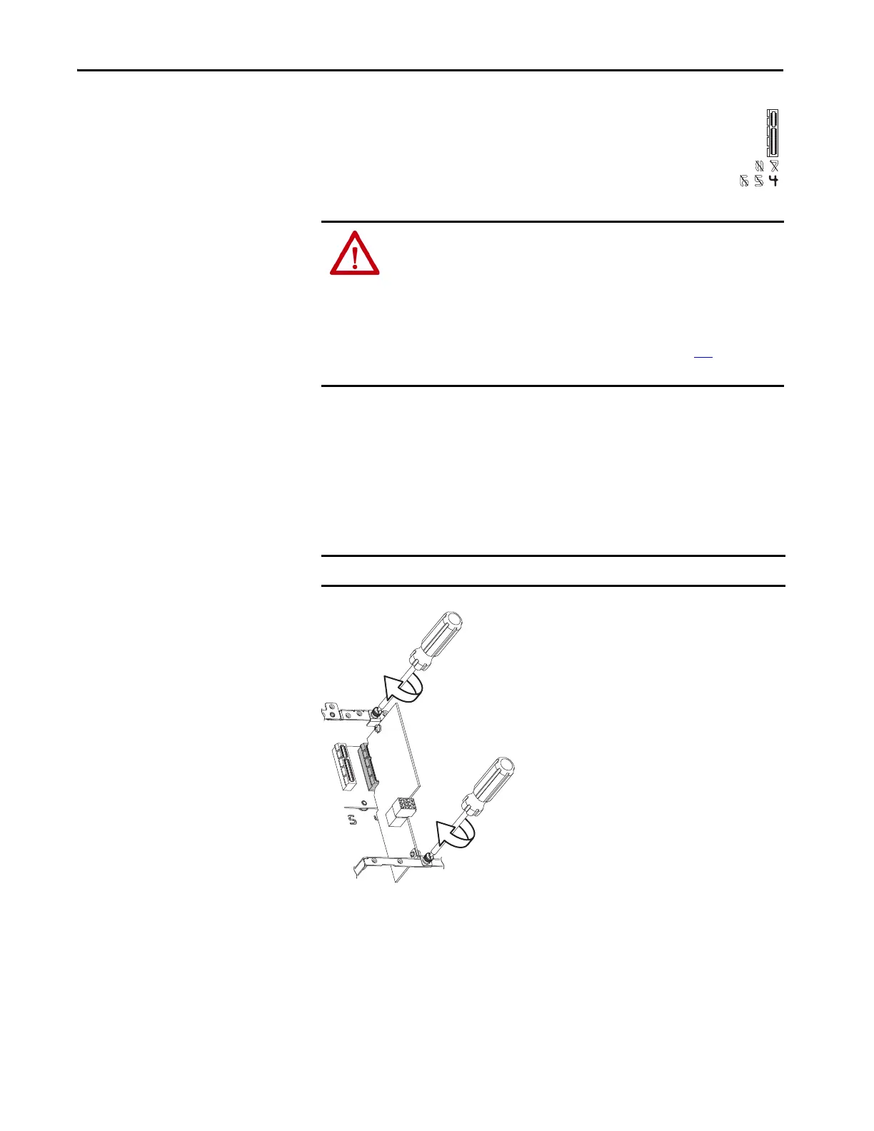
To install an option module:
1. Firmly press the module edge connector into the desired port.
2. Tighten the top and bottom retaining screws.
– Recommended torque = 0.45 N•m (4.0 lb•in)
– Recommended screwdriver = T15
ATTENTION: Hazard of equipment damage exists if an option module is
installed or removed while the drive is powered. To avoid damaging the
drive, verify that the voltage on the bus capacitors has discharged
completely and all control power is removed before performing any work on
the drive.
Measure the DC bus voltage at the DC+ and DC- TESTPOINT sockets on the front
of the power module (refer to the diagrams starting on page 102
for locations).
The voltage must be zero.
IMPORTANT Do not over-tighten retaining screws.

 Loading...


