Rockwell Automation Publication 750-IN100B-EN-P - July 2017 145
I/O Wiring Chapter 6
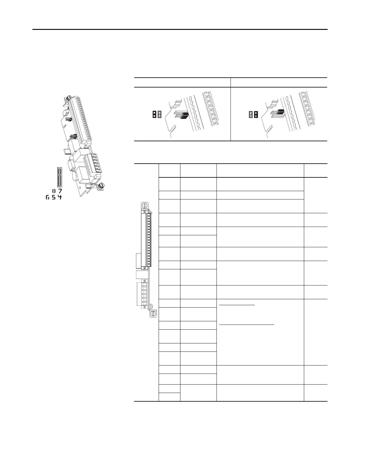
11-Series I/O Module
20-750-1132C-2R (24 Volts DC)
20-750-1133C-1R2T
Table 23 - Analog Input Mode Jumpers
Voltage Mode Current Mode
Table 24 - TB1 Terminal Designations
Terminal Name Description Related
Param
(4)
(4) I/O Module parameters will also have a Port designation.
–10V –10 Volt Reference Negative 10V DC for analog inputs. 2k ohm
minimum.
10VC 10 Volt Common For (–) and (+) 10 Volt references.
+10V +10 Volt Reference Positive 10V DC for analog inputs. 2k ohm
minimum.
Sh Shield Terminating point for wire shields when an EMC
plate or conduit box is not installed.
Ao0– Analog Out 0 (–) Bipolar, ±10V, 11 bit & sign, 2 k ohm minimum
load.
4-20 mA, 11 bit & sign, 400 ohm maximum load.
75
on Port nn
Ao0+ Analog Out 0 (+)
Sh Shield Terminating point for wire shields when an EMC
plate or conduit box is not installed.
Ai0– Analog Input 0 (–) Differential
(2)
, bipolar, 11 bit & sign.
Voltage Mode: ±10V @ 88k ohm input impedance.
Current Mode: 0-20 mA @ 93 ohm input
impedance.
(2) Differential - External source must be maintained at less than 160V with respect to PE. Input provides high common mode
immunity.
50, 70
on Port nn
Ai0+ Analog Input 0 (+)
Sh Shield Terminating point for wire shields when an EMC
plate or conduit box is not installed.
Di0 Digital Input 0 24V DC (30V DC Max.)
- Opto isolated
High State: 20…24V DC 11.2 mA DC
Low State: 0…5V DC
120V AC (132V AC Max.) 50/60 Hz
(3)
- Opto
isolated
High State: 100…132V AC
Low State: 0…30V AC
(3) For CE compliance use shielded cable. Cable length should not exceed 30 m (98 ft).
1
on Port nn
Di0P Digital Input 0
Power
(1)
(1) Digital Inputs are either 24 Volts DC (1132C) or 120 Volts AC (1132D) based on module catalog number. Ensure applied voltage is
correct for I/O module.
Di1 Digital Input 1
Di1P Digital Input
1Power
(1)
Di2 Digital Input 2
Di2P Digital Input 2
Power
(1)
Ip Input Power External 24V DC or 115V AC power supply input
connections. Does not power the main control
board.
Ic Input Common
EnC Enable Output ATEX fault enable output. Used only when an ATEX
option module is installed.
EnNO
P4
P4
–10V
10VC
+10V
Sh
Ao0–
Ao0+
Sh
Ai0–
Ai0+
Sh
Di0
Di0P
Di1
Di1P
Di2
Di2P
Ip
Ic
EnC
EnNO

 Loading...


