Rockwell Automation Publication 750-IN100B-EN-P - July 2017 177
I/O Wiring Chapter 6
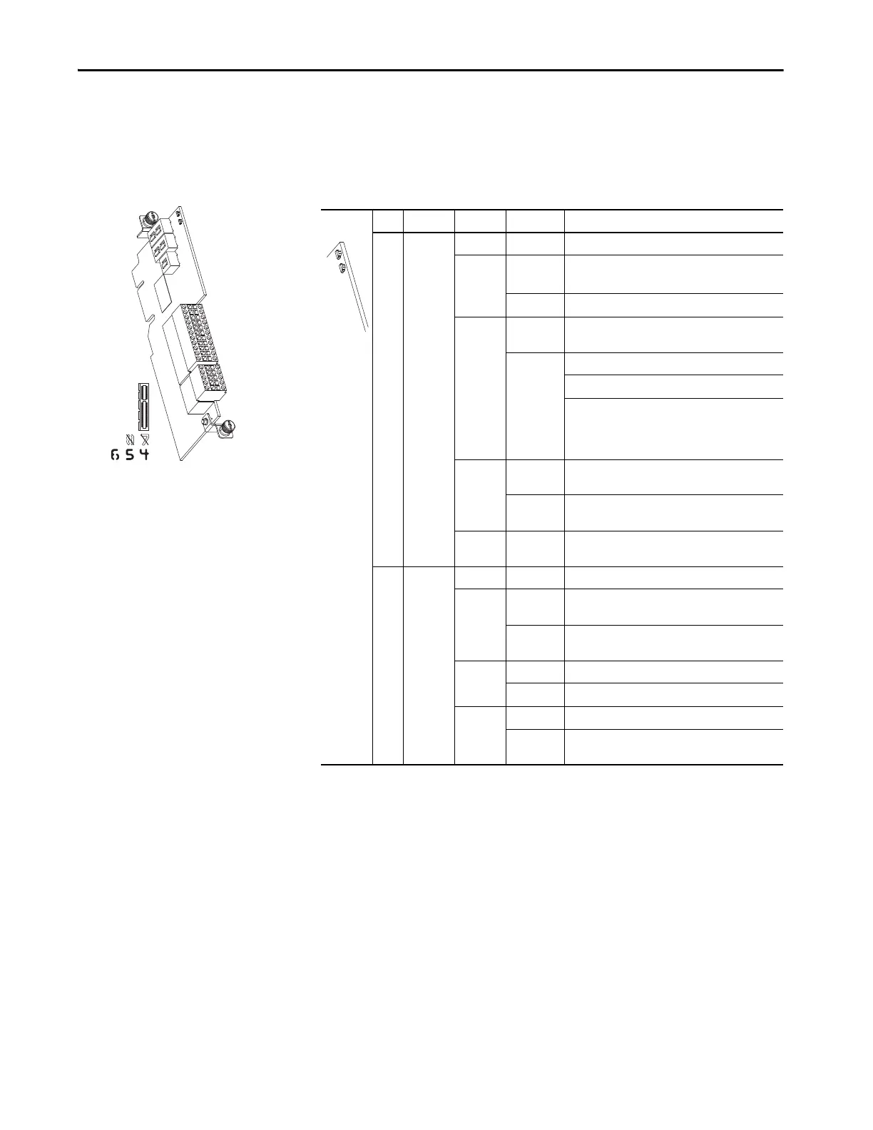
Universal Feedback Option
Module
Table 63 - Universal Feedback Option Module LED Indication
LED Name Color State Description
1 Board Unlit Off Not powered.
Green Flashing Initializing, not active.
Communication lost, attempting to reconnect.
Steady Operational, no faults are present.
Red Flashing Module error.
• Check 1 [Module Sts]
Steady Normal operation.
Module is booting.
Fatal module error.
• Cycle power
•Flash update module firmware
• Replace module
Yellow Flashing A type 2 alarm condition exists.
• Check 1 [Module Sts]
Steady A type 1 alarm condition exists.
• Check 1 [Module Sts]
Yellow /
Green
Flashing
Alternately
Module is flash updating.
2 DPI Unlit Off Not powered. Not communicating.
Green Flashing Module is attempting to communicate with the DPI
host.
Steady • Properly connected and communicating.
• Module is flash updating.
Red Flashing Module is not communicating with the DPI host.
Steady DPI communication failure such as invalid port.
Yellow Flashing Normal operation.
Steady Peripheral is connected to a SCANport product and
does not support a SCANport compatibility mode.

 Loading...


