110 Rockwell Automation Publication 750-IN100B-EN-P - July 2017
Chapter 5 Power Wiring
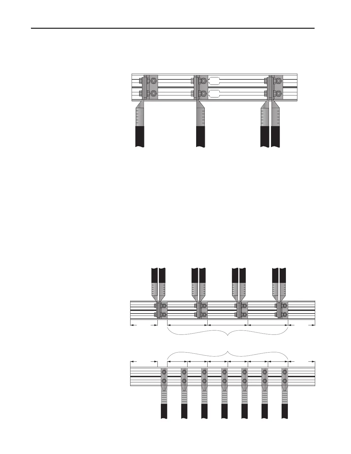
When using mechanical barrel lugs, which may be large, be sure to maintain
adequate spacing to adjacent wires, terminals, and other parts.
Figure 59 - Typical Barrel Lug Connection to L-Bracket Options
Recommended Cable Spacing
PowerFlex 755T products require multiple conductors in parallel. Wire size
and number of conductors must be determined by the customer based on drive
rated current, local codes, operating conditions, and specific application needs.
When using multiple conductors per phase, symmetrical spacing of the input
and output power cabling over the span of the bus bar for each phase is
required.
When using multiple conductors per phase, wires must be arranged so that
each conduit, bundle, or cable contains equal numbers of conductors from all
three phases.
Figure 60 - Spacing Examples
Left Side Right Side Both Sides - Up to four lugs.
5.1 mm
(2.0 in.)
5.1 mm
(2.0 in.)
5.1 mm
(2.0 in.)
5.1 mm
(2.0 in.)
Evenly space conductors along the length of the bus bar.
Maintain
clearance at
each end of the
bus bar.
Maintain
clearance at
each end of the
bus bar.

 Loading...


