70 Rockwell Automation Publication 750-IN100B-EN-P - July 2017
Chapter 4 Mechanical and Electrical Installation
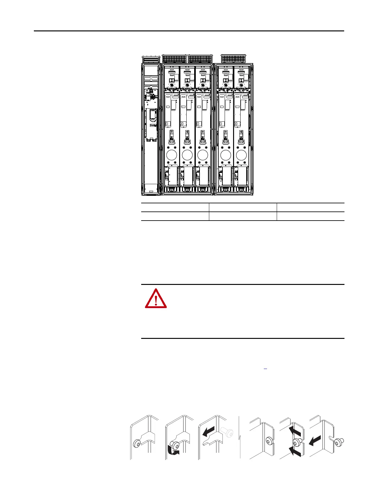
Figure 33 - Frame 12 Common Bus Inverter
Remove Protective Guards
You must remove the protective guards to access other components inside a
product enclosure. This section covers the removal procedure for each of the
enclosure types and enclosure widths. Follow the procedures to remove and
replace the protective guards.
Follow these steps to remove and replace the input bay protective touch guards.
1. Review the General Precautions on page 7
.
2. Open the enclosure door.
3. Loosen the M5.5 screws that secure the protective guards.
It is not necessary to remove these screws.
When you reinstall the guards, tighten the screws to the torque listed.
Module Type Remove Position No. Shipping Split Section
Motor side inverter M0, M1, M2, M3, M4 Section 1 of 1
ATTENTION: Hazard of personal injury or equipment damage exists when
protective touch guards are removed. Guards help to protect against
accidental contact with exposed electrical connections and components.
Guards can also provide electrical insulation between components. Remove
guards only when access is required. Replace guards promptly. Never operate
PowerFlex 755T products without all guards in place.

 Loading...


