EasyManuals Logo
Home>Allen-Bradley>Adapter>PowerFlex 755T

Allen-Bradley PowerFlex 755T Installation Instructions

Allen-Bradley PowerFlex 755T
192 pages
To Next Page IconTo Next Page
To Previous Page IconTo Previous Page
Page #96 background imageLoading...
Page #96 background image
96 Rockwell Automation Publication 750-IN100B-EN-P - July 2017
Chapter 4 Mechanical and Electrical Installation
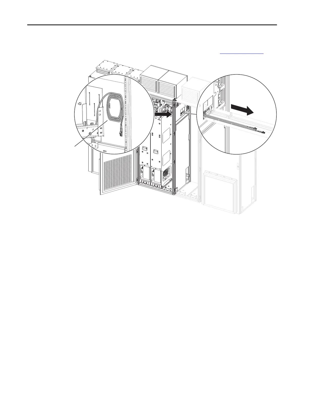
Fiber-optic Connections
Fiber-optic cables are stored on the right interior panel of the first power bay.
These cables connect the fiber interface board to the line side converters and
motor side inverters in the adjacent enclosures. See Figure 42 on page 80
.
1. Carefully uncoil the fiber-optic cables and pull them through the power
control channel into the adjacent enclosure.
Fiber-optic cables are
stored in a coil inside
the first power bay.

Table of Contents

Other manuals for Allen-Bradley PowerFlex 755T

Questions and Answers:

Question and Answer IconNeed help?

Do you have a question about the Allen-Bradley PowerFlex 755T and is the answer not in the manual?

Allen-Bradley PowerFlex 755T Specifications

General IconGeneral
BrandAllen-Bradley
ModelPowerFlex 755T
CategoryAdapter
LanguageEnglish

Related product manuals