EasyManuals Logo
Home>Allen-Bradley>Adapter>PowerFlex 755T

Allen-Bradley PowerFlex 755T Installation Instructions

Allen-Bradley PowerFlex 755T
192 pages
To Next Page IconTo Next Page
To Previous Page IconTo Previous Page
Page #65 background imageLoading...
Page #65 background image
Rockwell Automation Publication 750-IN100B-EN-P - July 2017 65
Mechanical and Electrical Installation Chapter 4
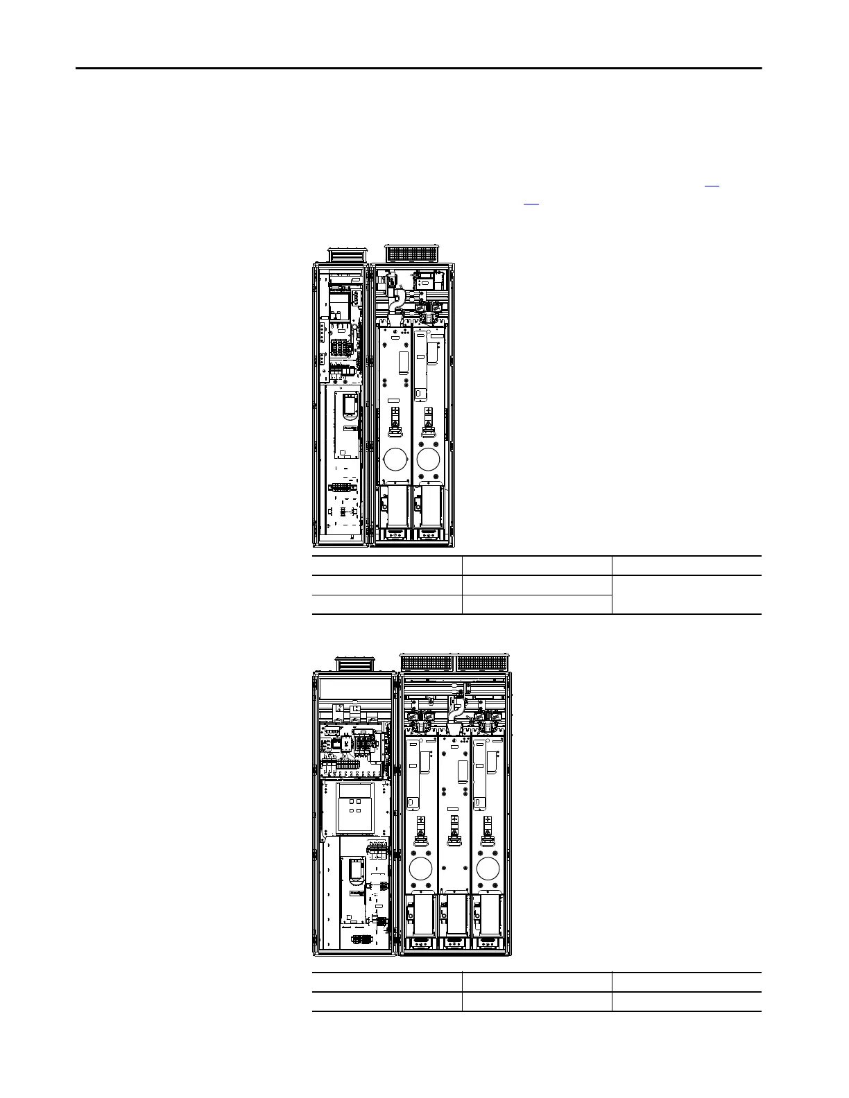
PowerFlex 755TM Bus Supplies
This section lists the LCL filter modules and line side converters that you must
remove to install the product. For instructions on how to remove these
components from the enclosure, see Remove Power Module on page 73
and
Remove LCL Filter Module on page 79
.
Figure 24 - Frame 8 Bus Supply
Figure 25 - Frame 9 Bus Supply
Module Type Remove Position No. Shipping Split Section
LCL filter LCL0 Section 1 of 1
Line side converter L0
Module Type Remove Position No. Shipping Split Section
Line side converter L0, L1 Section 1 of 1
L0LCL0
L1L0

Table of Contents

Other manuals for Allen-Bradley PowerFlex 755T

Questions and Answers:

Question and Answer IconNeed help?

Do you have a question about the Allen-Bradley PowerFlex 755T and is the answer not in the manual?

Allen-Bradley PowerFlex 755T Specifications

General IconGeneral
BrandAllen-Bradley
ModelPowerFlex 755T
CategoryAdapter
LanguageEnglish

Related product manuals