78 Rockwell Automation Publication 750-IN100B-EN-P - July 2017
Chapter 4 Mechanical and Electrical Installation
Install Power Modules in the Enclosure
Install the power modules into the enclosure in the reverse order of removal.
When you install the fiber-optic cables:
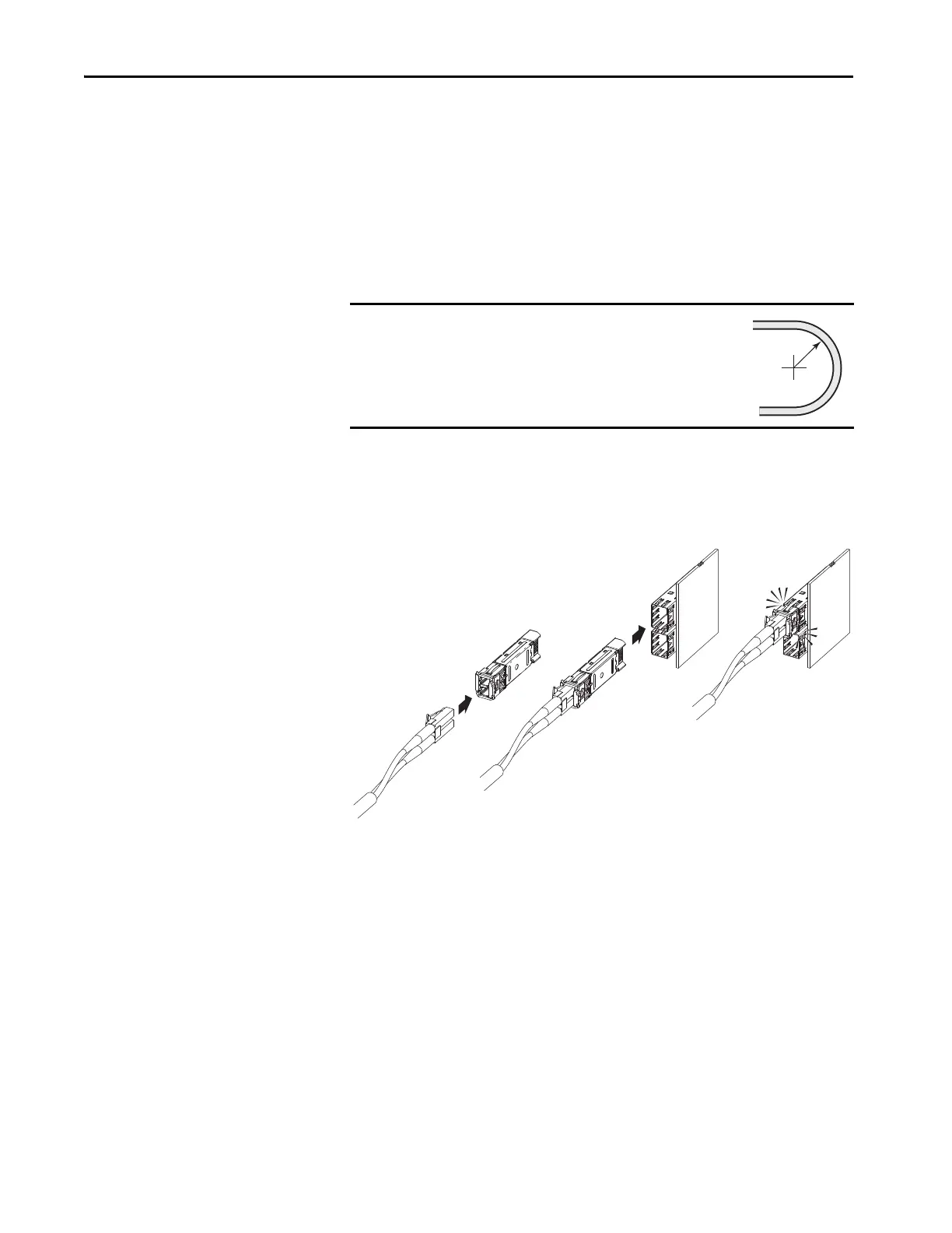
1. Remove the transceiver from the fiber-optic connector port on the
power layer interface circuit board.
2. Without bending the cable to a radius less than 50 mm (2 in.), fully
insert the fiber-optic cable into the transceiver.
3. Insert the transceiver and fiber-optic cable into the connector on the
board, until you hear an audible ‘click.’
Be sure that both plugs are completely engaged and seated and that the
swing arm is down.
IMPORTANT
Minimum inside bend radius for fiber-optic cable is
50 mm (2 in.). Any bends with a shorter inside radius
can permanently damage the fiber-optic cable. Signal
attenuation increases as inside bend radius is
decreased.

 Loading...


