Rockwell Automation Publication 750-IN100B-EN-P - July 2017 153
I/O Wiring Chapter 6
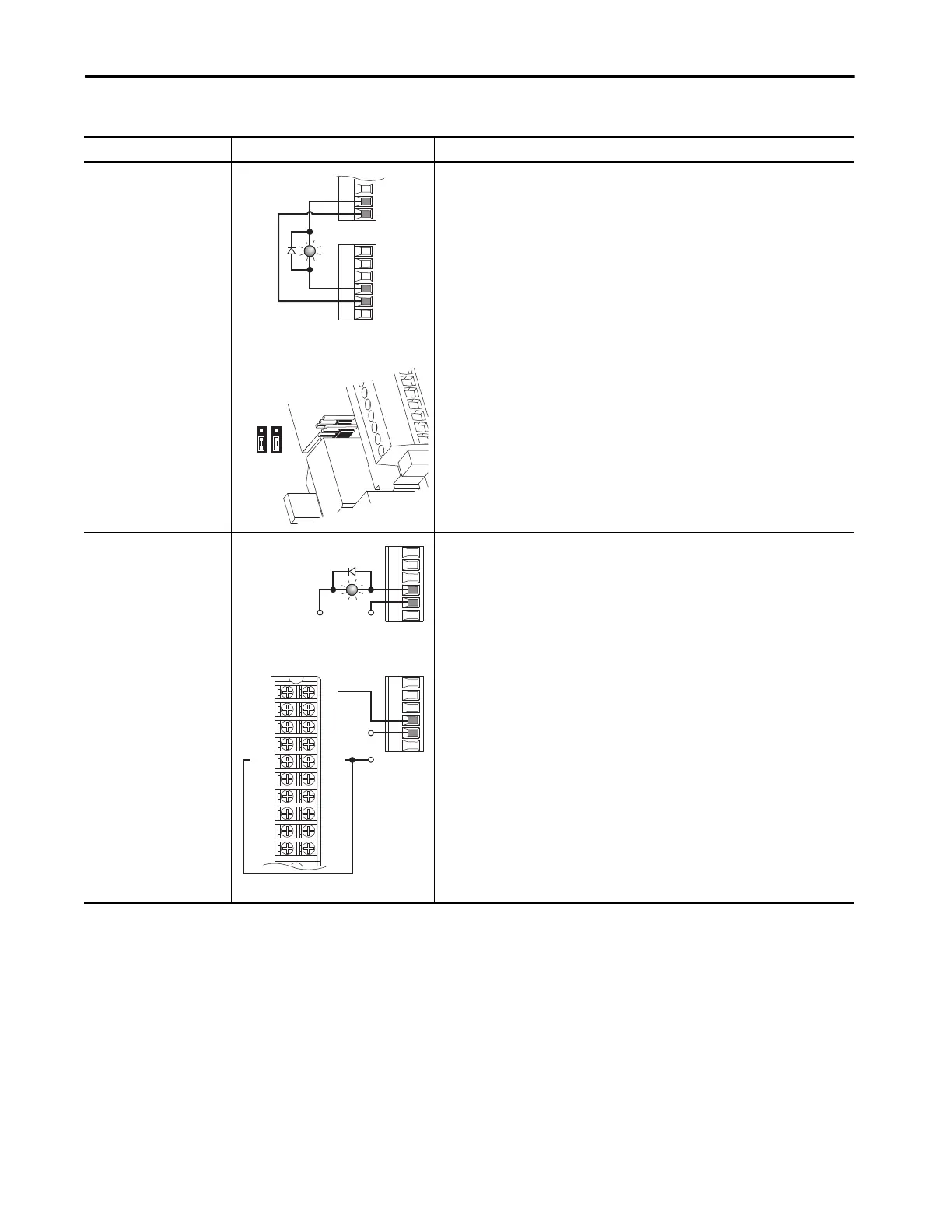
Digital Output
Internal supply
20-750-1133C-1R2T
Main Control Board TB1
11-Series I/O Module TB2
•Set Selection
Port nn:20 [TO0 Sel] (11-Series I/O Module) = Port 10/11:354 [Motor Side Sts 1], bit 7 =
Faulted
• View Results
Port nn:5 [Dig Out Sts] (11-Series I/O Module)
Digital Output
External supply
20-750-1133C-1R2T
PLC TB 11-Series I/O Module TB2
•Set Selection
Port nn:20 [TO0 Sel] (11-Series I/O Module) = Port 10/11:354 [Motor Side Sts 1], bit 7 =
Faulted
• View Results
Port nn:5 [Dig Out Sts] (11-Series I/O Module)
Table 28 - 11-Series I/O Module TB1 Wiring Examples (continued)
Input/Output Connection Example Required Parameter Changes
T1
+24V
P3
T0
TC
T1
T0
TC
T1
OR
+24VDC
Common
PLC
1756-1B16
IN-9
IN-11
IN-13
IN-15
GND-1
IN-1
IN-3
IN-5
IN-7
GND-0
IN-8
IN-10
IN-12
IN14
GND-1
IN-0
IN-2
IN-4
IN-6
GND-0

 Loading...


