EasyManuals Logo
Home>Allen-Bradley>Adapter>PowerFlex 755T

Allen-Bradley PowerFlex 755T Installation Instructions

Allen-Bradley PowerFlex 755T
192 pages
To Next Page IconTo Next Page
To Previous Page IconTo Previous Page
Page #172 background imageLoading...
Page #172 background image
172 Rockwell Automation Publication 750-IN100B-EN-P - July 2017
Chapter 6 I/O Wiring
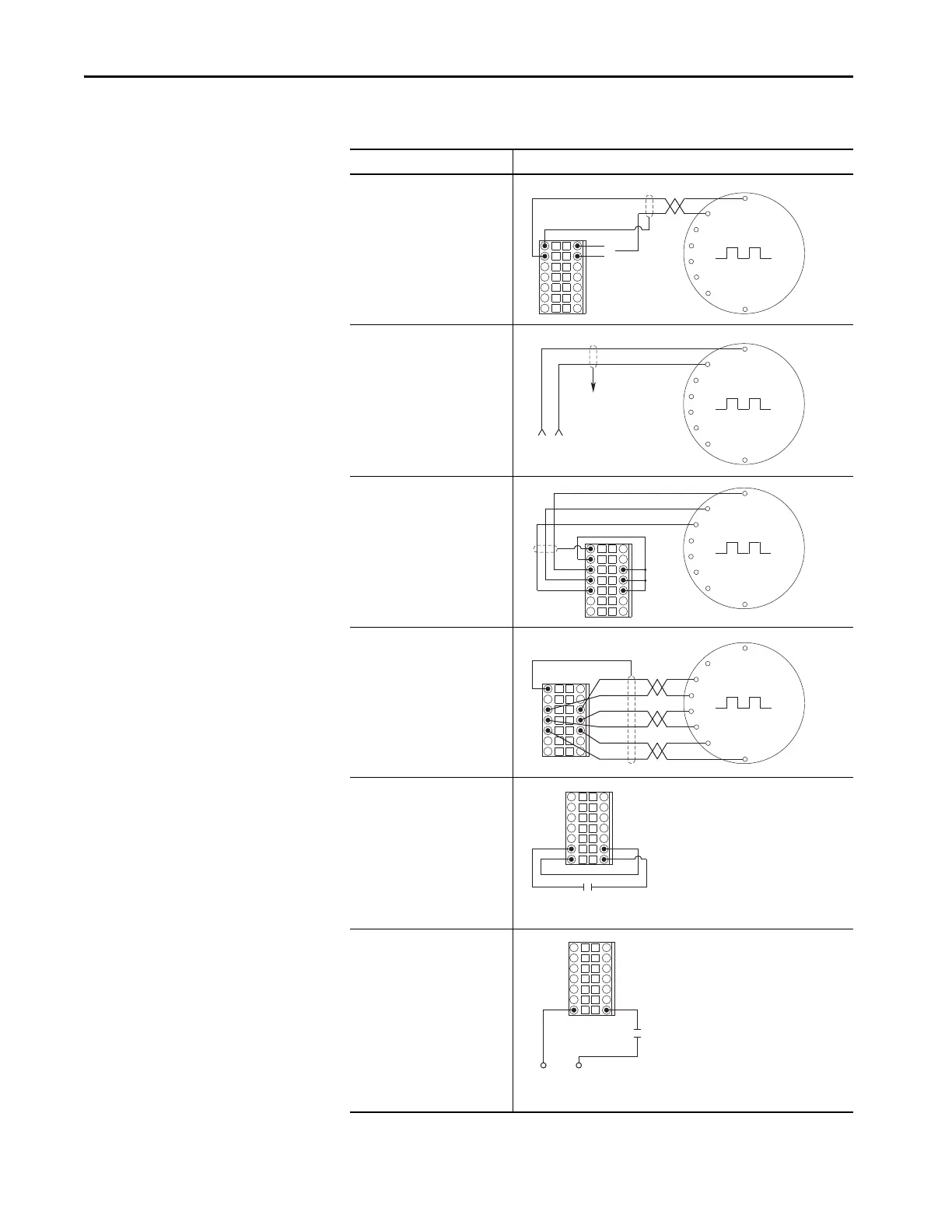
Table 59 - Single Incremental Encoder Sample Wiring
I/O Connection Example
Encoder Power by Drive
12V DC, 250 mA
OR
5V DC, 250 mA
Separately Powered Encoder
Encoder Signal –
Single-Ended, Dual Channel
Encoder Signal –
Differential, Dual Channel
Homing Signal –
Internal Drive Power
Homing Signal –
External Power
Com
+12
Sh
+5
VDC
Com
Sh
Com
A-
B-
Z-
A
B
Z
Sh
Z-
Z
Sh
B-
B
A-
A
HmC
+24V
24VC
Hm
Home Switch
HmC
Hm
Home Switch
Common +24V
External Power Supply

Table of Contents

Other manuals for Allen-Bradley PowerFlex 755T

Questions and Answers:

Question and Answer IconNeed help?

Do you have a question about the Allen-Bradley PowerFlex 755T and is the answer not in the manual?

Allen-Bradley PowerFlex 755T Specifications

General IconGeneral
BrandAllen-Bradley
ModelPowerFlex 755T
CategoryAdapter
LanguageEnglish

Related product manuals