Configura-
tion Value
Life Test
Jumper
Present
Comm
Board "B"
Header
Present
Comm
Board "A"
Header
Present
Vend Con-
nection
Present
Coin Drop
#2 Present
Coin Drop
#1 Present
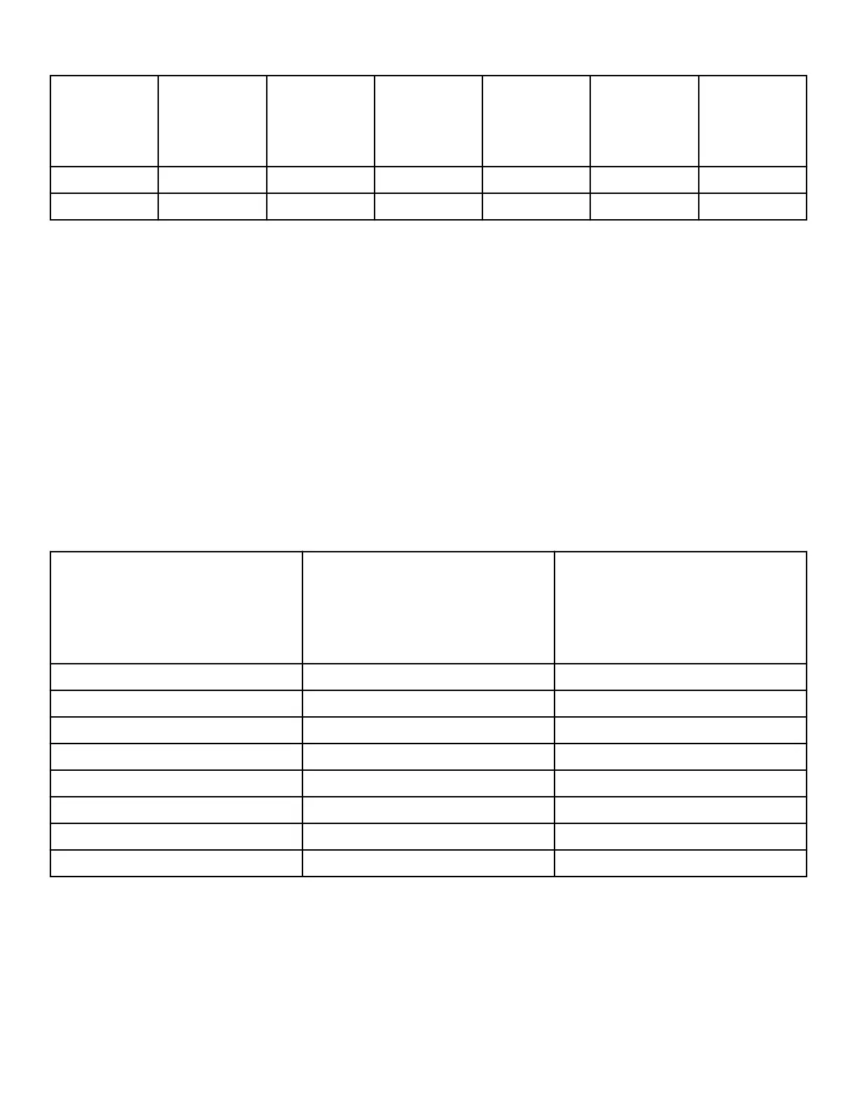
62 YES YES YES YES YES NO
63 YES YES YES YES YES YES
Table 15
Configuration 2 Display Test d 30
This option is not used on this model.
Configuration 3 Display Test d 31
This option is not used on this model.
Configuration 4 Display Test d 32
This option shows the user which dipswitches are set on the con-
trol.
To start test, control must be in the Testing Mode. Refer to How
to Enter Testing Feature at the beginning of this section.
To Enter, press the START (enter) keypad. The display will show
d XXX with XXX representing a configuration value as shown
in Table 16 .
If supply voltage is 100-127 Volt per phase, the voltage configu-
ration should be 120 Volt.
If supply voltage is 200-240 Volt per phase, the voltage configu-
ration should be 240 Volt.
To exit Machine Configuration 4 Display Test, press the WARM
(<) keypad. The control will return to the Testing Mode.
Each column in the table below contains a unique combination of
the words “ON” and “OFF” that indicates if that column’s dips-
witch is set on or off when the value is displayed. All other dips-
witches are not used.
Configuration Value
Dipswitch 3
Payment System Not Present
(OFF)
Payment System Present (ON)
Dipswitch 1
120 Volt Supply (OFF)
240 Volt Supply (ON)
0 OFF OFF
1 OFF ON
2 OFF OFF
3 OFF ON
4 ON OFF
5 ON ON
6 ON OFF
7 ON ON
Table 16
Configuration 5 Display Test d 33
This option is not used on this model.
Testing Machine and Electronic Control Functions
©
Copyright, Alliance Laundry Systems LLC -
DO NOT COPY or TRANSMIT
78 Part No. 204370ENR1
 Loading...