Power Commissioning
Commissioning Handbook, AutroSafe Interactive Fire Detection System, Release 4, 116-P-ASAFE-COMMISS/EGB Rev.F, 2014-04-01,
Autronica Fire and Security AS
Page 13
5.1.3 AutroFieldBus Addresses
Each AutroFieldBus unit/Power Board BSF-400 on an AutroFieldBus
must be assigned a unique address by means of an rotary switch (see
previous page).
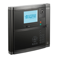
The drawing below shows the AutroFieldBus connections on the main
terminal block, list L1 mounted on a DIN rail inside the cabinet
(BS-420/BC-420). The first AutroFieldBus unit is connected to the
terminals L1.9 / L1.11 (AFB A). The last unit is connected to L1.3 /
L1.5 (AFB B).
CT (CenterTap) of transformer shall not be connected (terminal 3 and
11). Shield is connected to earth at one end only.
L1.3
L1.5
L1.7
L1.15
L1.9
L1.11
L1.13
Last AFB unit
First AFB unit
SA 400 with shielded AF cable
BSA-400 with unshielded AFB cable
L1.9
L1.11
Last AFB unit
A maximum of 31 AutroFieldBus units can be connected to one
AutroFieldBus, giving the number range 01 to 31. The physical
addresses are set by means of the rotary switches on the board.
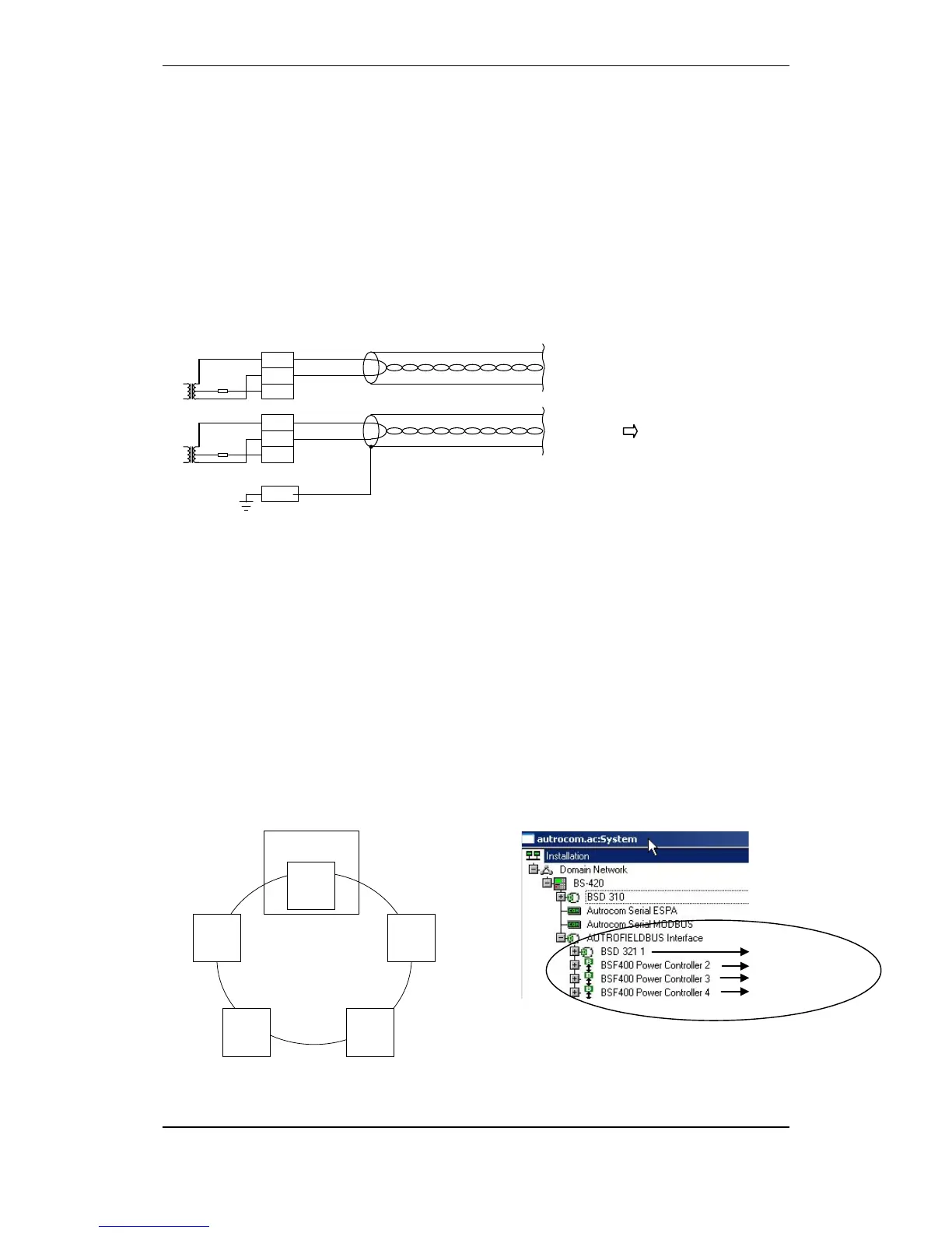
The illustration below shows an example of the system topology
window. 4 AutroFieldBus units are added to the AutroFieldBus
interface.
The sequence of the units in the topology window determines the
switch settings on each unit, i.e. the first unit (the uppermost unit in
the topology window) is to be given switch address 01, the next is to
be given switch address 02, and so on.
Note that the physical sequence of AutroFieldBus units on the
AutroFieldBus must not necessarily correspond to the sequence
shown in the topology window, however this is recommended.
Addressing AutroFieldBus units on the AutroFieldBus
Fire Alarm Control
Panel BS-420
BSA-400
BSF-400
BSD-321
BSF-400
AutroFieldBus
Switch
Address 01
BSF-400
Switch
Address 02
Switch
Address 03
Switch
Address 04
Always address 00
The first AutroFieldBus unit
Example: System topology window in
the AutroSafe Configuration Tool
Switch address 02
Switch address 03
Switch address 04
Main terminal block, list L1
 Loading...

