Verifying the System after
an Upload
Commissioning Handbook, AutroSafe Interactive Fire Detection System, Release 4, 116-P-ASAFE-COMMISS/EGB Rev.F, 2014-04-01,
Autronica Fire and Security AS
Page 37
Check the fault warning function from detector zones by removing a detector in each zone.
Activate a fault (remove battery fuse) and observe:
- the Fault indicator starts to blink
- a fault warning is displayed
- the internal buzzer is turned ON
- the Fault Warning Routing Equipment (FWRE) output is activated (if any)
Enable alarm transference to the Fire Alarm Routing Equipment -FARE output.
9.2 Verifying Detection Loops During Normal Operation
It may be necessary to verify the detection loops (checking the loop
topology, the types of loop units, the location of loop units, the Loop
Sequence Indexes, etc.) during normal operation using the AS-2000
Loop Diagnostic Tool.
Before applying the tool, prepare the system for the verification as
follows:
Enter the Service Menu (5), select Upgrade (5), then Reboot
System (6).
The system will now enter system fault condition.
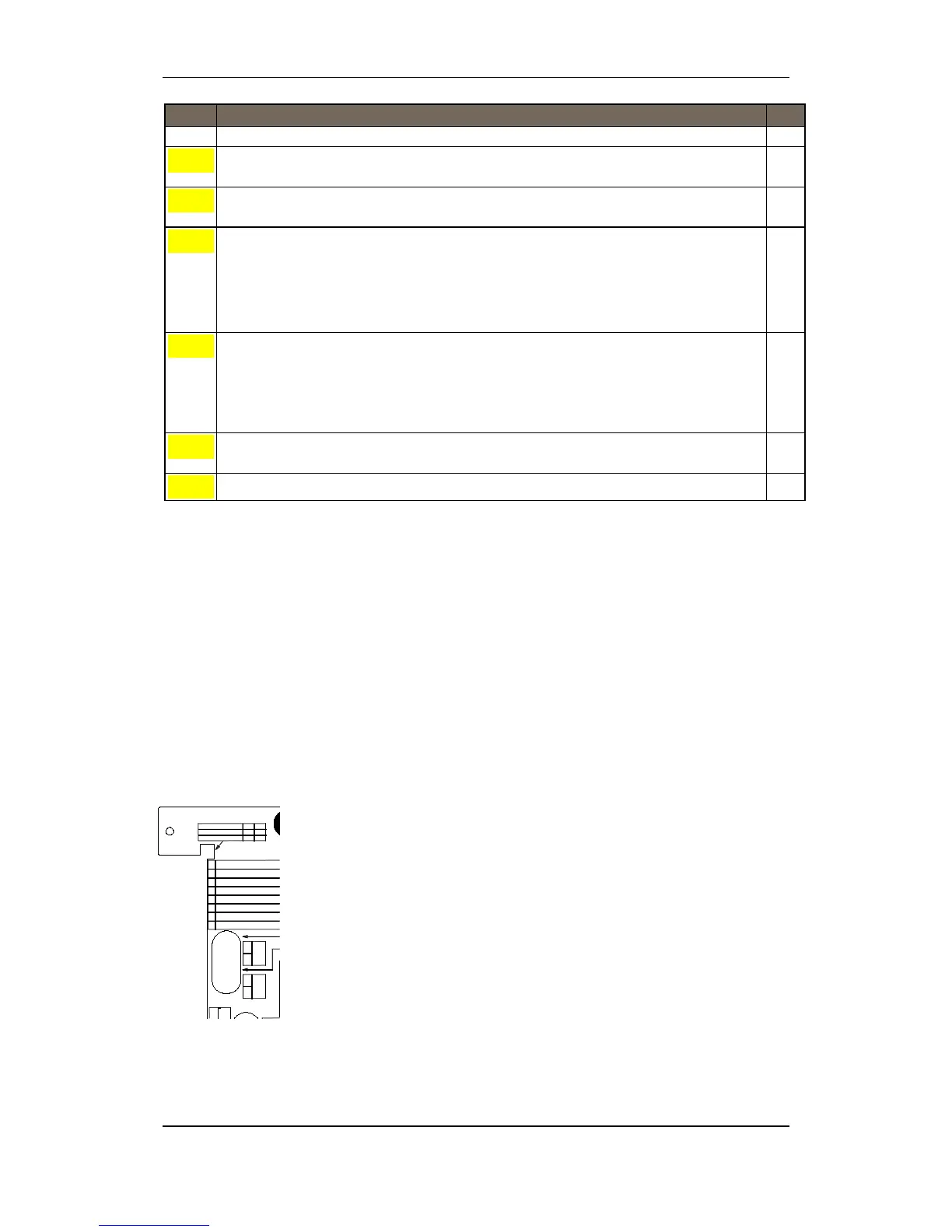
Remove fuse A1 and A2 from the Power Board BSF-400.
Connect and apply the tool, and do the necessary verifications.
Alternative 1:
Disconnect a detection loop. Use the AS-2000 Was-box to verify
the loop. Perform a verification for each loop in turn.
Alternative 2:
Disconnect the ribbon cable to BSL-310. Connect the AS-2000.
Run an initialization.
When the verification is completed, disconnect the tool/PC, re-
connect the cables, then re-place the fuses.
Reboot the system again.
 Loading...

