31.12
Assembly specification for telescopic fork:
e Caution:
To ensure that the fork is installed without trapped
stresses, observe the following instructions and the
specified working sequence precisely.
•
The front suspension strut is removed.
e Caution:
Protect painted parts from scratching: apply adhe-
sive masking tape if necessary.
•
Bolt fork bridge to frame.
X Tightening torque:
Fork bridge to ball joint
(clean thread + Loctite 2701)
[RS] .......................................................... 130 Nm
Threaded journal to frame
(clean thread + Loctite 243)
[GS/R/RT] ................................................. 130 Nm
•
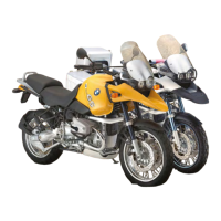
Pre-assemble fork legs with quick-release axle/
adjust distance A.
Distance A:.............165
± 0.5
mm (6.496
± 0.01969
in)
X Tightening torque::
Quick-release axle clamps ........................... 22 Nm
L Note:
If the quick-release axle was not removed, for in-
stance when only the fork slider tube bridge was re-
moved/installed, the above work stage is omitted.
•
Secure slider tube bridge/do not tighten to spec-
ified torque at this point.
•
Screw slider tube bridge to leading link.
X Tightening torque:
Leading link at ball joint
(clean thread + Loctite 2701)...................... 130 Nm
•
Using a strap or similar, pull fork towards frame
until the fully retracted fixed tubes only need to
be pulled out slightly to secure them to the fork
bridge. Secure fixed tubes to the fork bridge.
•
Secure fixed tubes to the fork bridge.
X Tightening torque:
Clamp between fixed tubes and fork bridge
[RS] ............................................................. 22 Nm
Screw connection between fixed tube and fork
bridge (oil/grease free)
[GS/R/RT].................................................... 45 Nm
•
Tighten down slider tube bridge.
X Tightening torque:
Bridge to fork slider (clean thread +
Loctite 243).................................................. 22 Nm
•
Check that the system moves freely by com-
pressing and extending the suspension (but
without the suspension strut) in the straight-
ahead and left/right steering lock positions.
•
Remove quick-release axle.
e Caution:
When being reassembled, the quick-release axle
must well aligned; it should be possible to install it
by rotating it slightly.
•
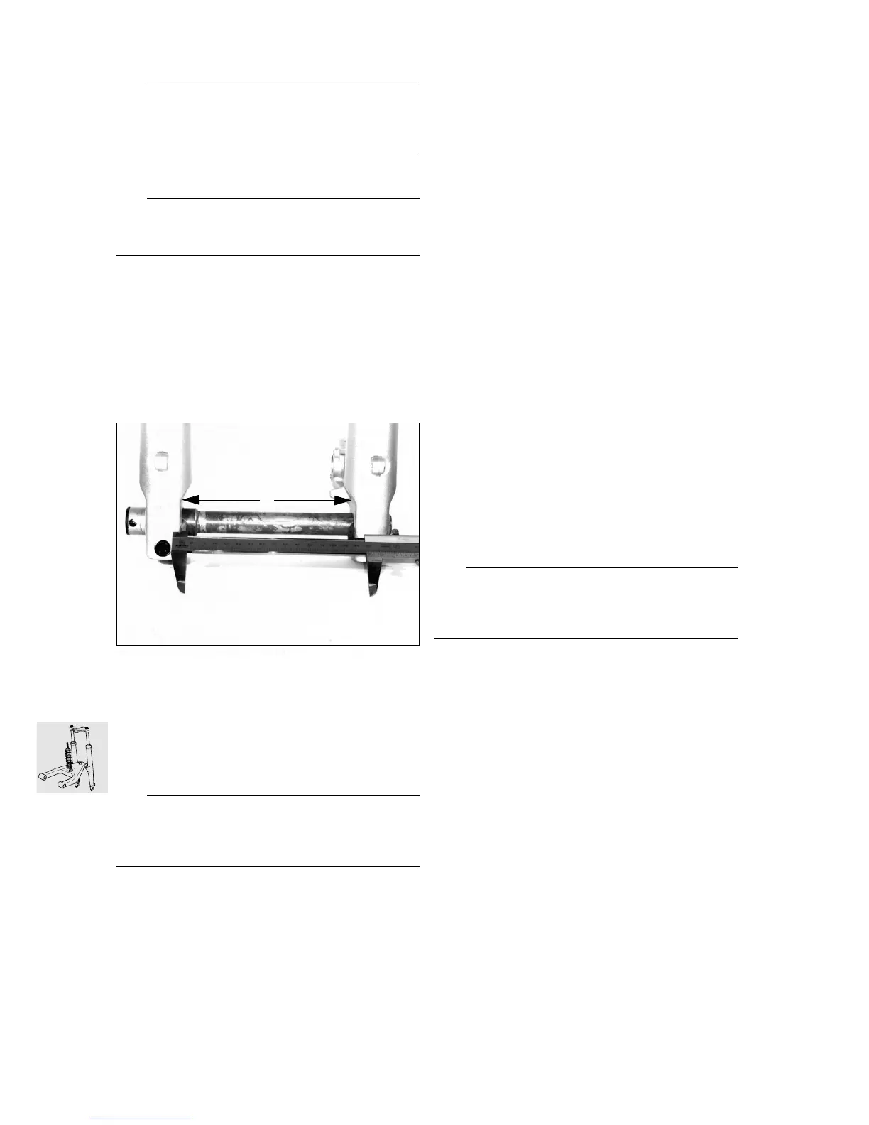
Install suspension strut.
X Tightening torque::
Spring strut to frame .................................... 47 Nm
Spring strut to leading link
[RS] (8.8 bolt)............................................... 43 Nm
[RS] (10.9 bolt)............................................. 50 Nm
[GS/R/RT] (10.9 bolt)................................... 50 Nm
A
GS310140
 Loading...