D9412G/D7412G | Program Entry Guide | 4.0 RADXPNTS EN | 91
Bosch Security Systems | 10/03 | 47775E
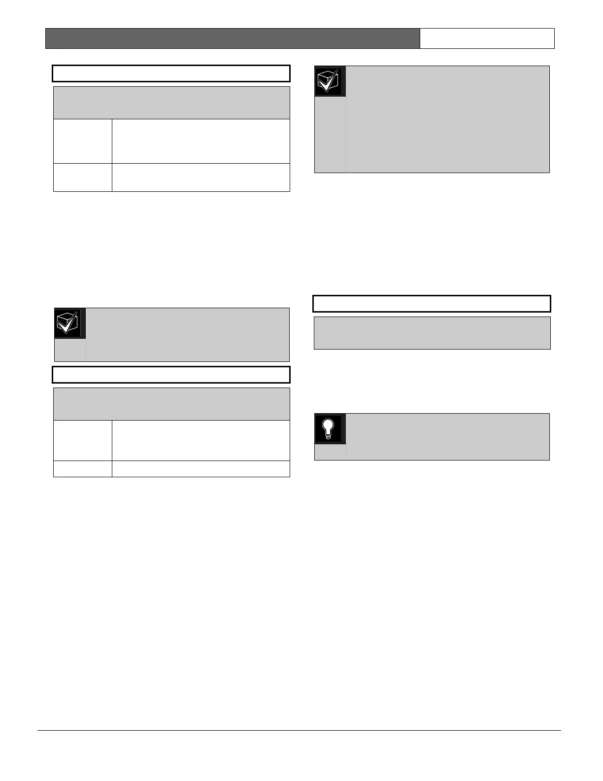
P## Alarm Verify
Default: See
Program Record Sheet
Selection: Yes or No
Yes Enable alarm verification on this point.
Alarm verification points must be
programmed as resettable.
No Disable alarm verification on this
point.
Use this option only with Fire points to designate
them for alarm verification.
When an Alarm Verification point goes into alarm,
the control panel removes power to all Resettable
points for the duration programmed in
A# Verify
Time
in Section 2.9 Area Parameters. If the point (or
another Resettable point in the area) is still in alarm,
or goes back into alarm within 60 seconds after the
initial verification time reset, an alarm is generated.
During a Fire Walk Test the reset time is 5
seconds. The time programmed in A#
Verify Time is ignored. Use the Cross
point function for Fire points.
P## Resettable
Default: See
Program Record Sheet
Selection: Yes or No
Yes This point is reset by the Reset Sensor?
function and during the alarm
verification sequence.
No This point is not resettable.
Use this option if this is a Powered point that
requires interruption of power to reset a latched
alarm condition. The Resettable point option is
typically used with smoke detectors and glass break
detectors.
When initiated (either through a Fire Walk Test or
the command center’s Reset Sensor? Function) or
when the RAM interrupts power to the device for 5
seconds, Sensor Reset is reported to the central
station receiver.
When a sensor reset is initiated, the
control panel does not accept alarms from
any points with P## Resettable
programmed as Yes. During the 5-second
reset time, alarms from these points are
ignored.
Do not mix fire and intrusion devices on
the same powered loop.
4.2 Point Assignments
These entries assign point indexes to Points 1 to 127,
129 to 247 for the D9412G and Points 1 to 75 for the
D7412G, and assigns the points to the areas. Also
included in this section are parameters used to set
the point’s debounce count, BFSK/Relay (for use
when transmitting in BFSK or assigning relays to
follow alarms for a group of points), and custom
command center and report text for each point.
Point Number
Default: 1
Selection: 1 to 127, 129 to 247
Enter the point number you are programming.
When transmitting in Modem IIIa
2
, the three-digit
point number is reported to the D6500/D6600.
When transmitting in BFSK, you must assign a zone
number in BFSK/Relay.
0101
0101
0101
Point numbers 128 and 248 are reserved
for Zonex bus 1 and 2 supervision.

 Loading...


