100 Section 4: Symptoms
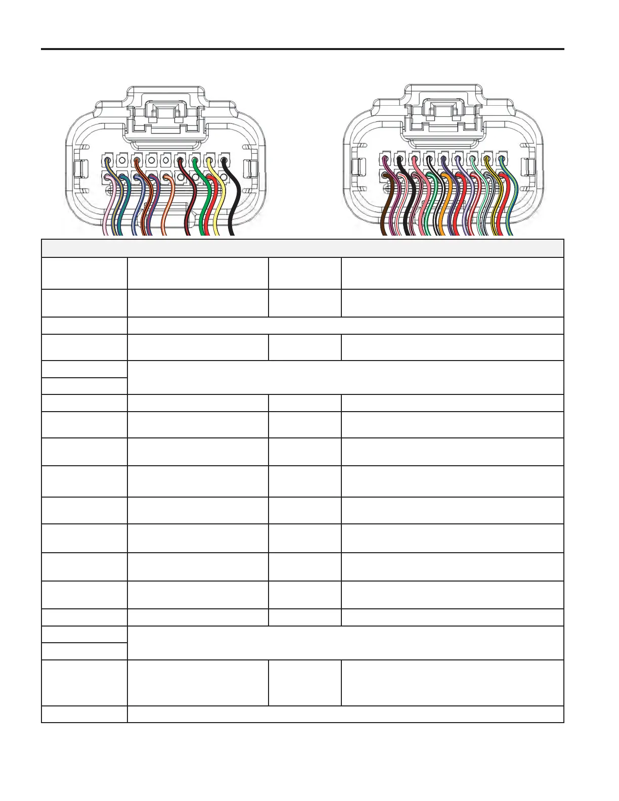
ECM Connector J1 (Grey)
Connector-
Pin Number
Function Wire Color
Possible Symptom
From Faulty Circuit
J1-01
IAC HIGH “A”
*
Idle Air Control A High
Blue/Brown
Rough, unstable, or incorrect idle
J1-02
NOT USED
J1-03
MIL
Malfunction Indicator Lamp
Orange/Black
MIL inoperative
J1-04
NOT USED
J1-05
J1-06 Tachometer
Black/Red
Tachometer inoperative
J1-07
CAN Low
Used only for ECM Development
Green
No Can Signal
J1-08
CAN High
Used only for ECM Development
Yellow
No Can Signal
J1-09
GROUND
Power
Black
An open ground or high resistance
ground may cause any or all symptoms
J1-10
IGN COIL CYL 2
Engine Spark Timing Coil Cylinder 2
Violet/White
Rough idle, lack of power, stalling
J1-11
IAC LOW “A”
*
Idle Air Control A Low
Blue/Green
Rough, unstable, or incorrect idle
J1-12
IAC HIGH “B”
*
Idle Air Control B High
Blue/Grey
Rough, unstable, or incorrect idle
J1-13
IAC LOW “B”
*
Idle Air Control B Low
Blue/Red
Rough, unstable, or incorrect idle
J1-14 Safety Interrupt Circuit
Orange/White
No start
J1-15
NOT USED
J1-16
J1-17
MPR
Main Power Relay
Red
An open B+ circuit or high resistance
in the B+ circuit may cause any or all
symptoms
J1-18
NOT USED
* If Equipped
(See Table at Bottom of Page 11)
ECM Connector Symptoms
1
9
10
18
ECM J1
1
9
10
18
ECM J2
 Loading...