Section 5: Removal/Installation 125
7. Disconnect TPS connector.
Installation
1. Connect TPS connector.
2. Connect IAC connector.
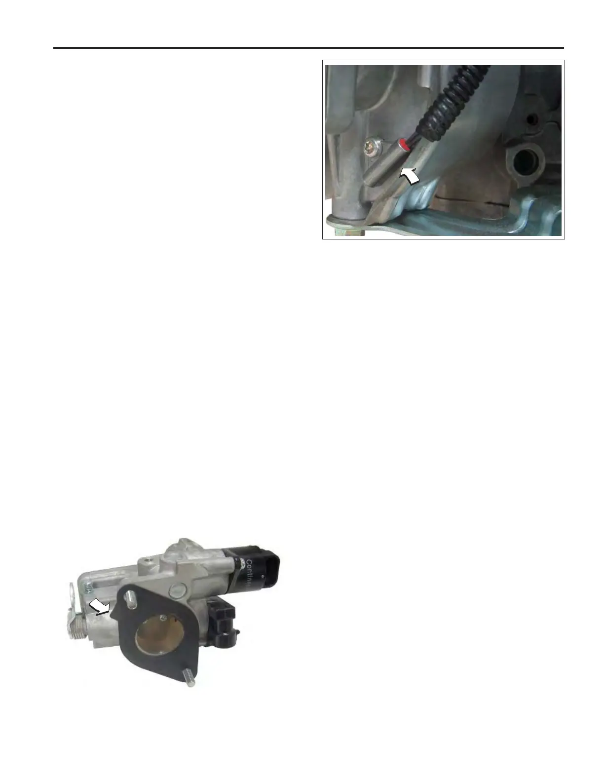
3. Install two hex fl ange screws in throttle
body fl anges. Hang new gasket on screws,
so that tab points toward idle screw with
spring. See Figure 5-21.
4. Start hex fl ange screws into intake mani-
fold. Alternately tighten screws to 78-96
in-lbs (9-11 Nm).
5. Install hex fl ange screw to fasten ECM/
fuse block bracket to throttle body. Tighten
screw until snug.
6. See Air Cleaner Assembly, Installation.
7. Tighten ECM/fuse block bracket to throttle
body screw to 78-96 in-lbs (9-11 Nm).
8. Slide Phillips screw through ECM fl ange
(Grey ECM J1 connector side) and ground
wire ring terminal. Start screw into ECM/
fuse block bracket.
9. Install second Phillips screw on opposite
side, and alternately tighten screws to 35-
52 in-lbs (4-6 Nm).
10. Install access cover. See Access Cover/
Blower Housing, Installation, steps 7-10.
EHT Sensor
NOTE: The EHT sensor is an integral part of
the EFI wire harness and is not sold sepa-
rately. Replace EFI wire harness if EHT sensor
is bad.
EFI Wire Harness
Removal
1. See Access Cover/Blower Housing, Re-
moval.
2. See Air Cleaner Assembly, Removal.
3. See A of Figure 5-23. On cylinder 2 side of
engine, proceed as follows:
• Remove screw to release fuse block cover
from ECM/fuse block bracket.
• Disconnect MAP/MAT sensor connector.
• Disconnect fuel injector connector.
• Disconnect ignition coil connector.
• Remove Phillips screw to release ground
wire ring terminal from cylinder boss.
• Disconnect ECM J2 connector.
Figure 5-21 Throttle Body Gasket.
Figure 5-22 EHT Sensor.
 Loading...