12 Section 2: Troubleshooting DTCs
ECM
Cylinder 2
Ignition Coil
Cylinder 1
Ignition Coil
Cylinder 2
Fuel Injector
Cylinder 1
Fuel Injector
ECM
DLC
Fuse/Relay Block
MAP/MAT
Sensor
EHT
Sensor
CKP
Sensor
HO
2
Sensor
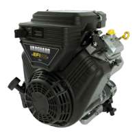
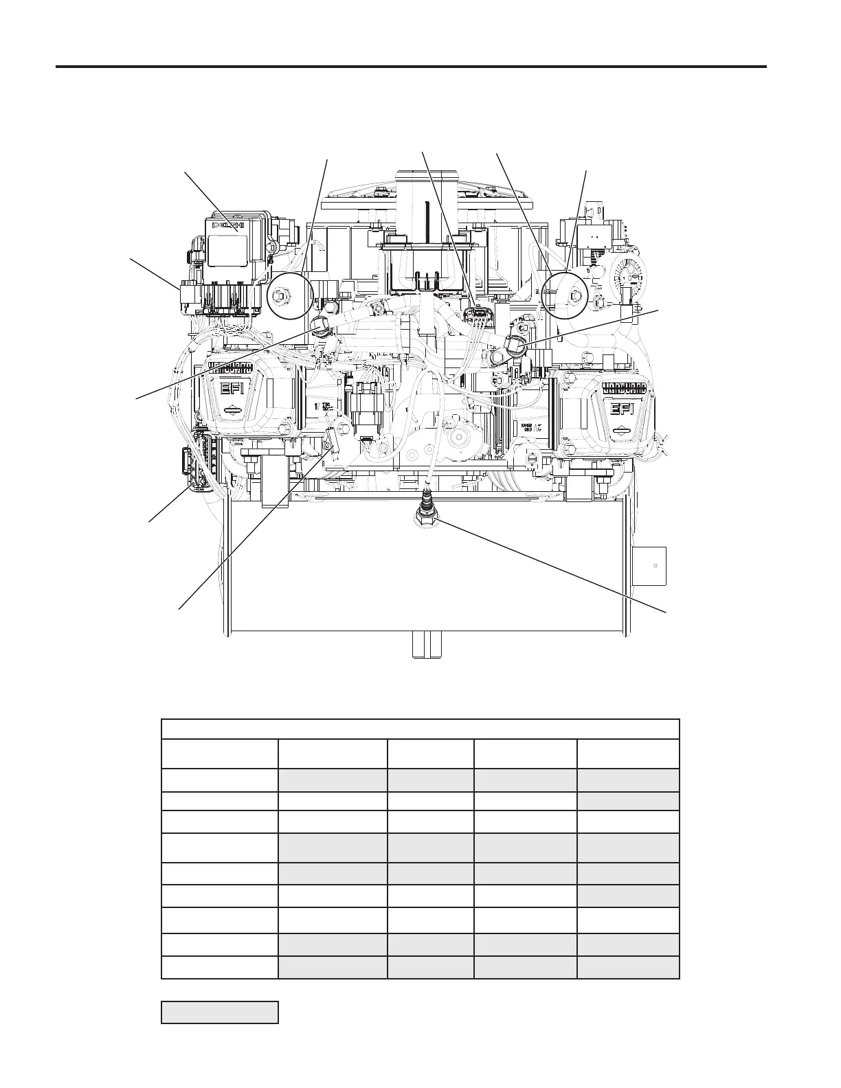
Model 490000 EFI Component Locations
Figure 2-1 Model 490000 Components.
(Static Guard, Decorative Cover, and Blower Housing Removed for Illustration Purposes.)
Disassembly Required for Back Probing Connector (x) or Replacing Component (o)
To Access
Remove
Air Cleaner Assembly
Remove
Static Guard
Remove
Decorative Cover
Remove
Blower Housing
ECM
MAP/MAT Sensor
xo xo xo
Ignition Coil
ooo o
Mechanical Diaphragm
Fuel Pump
Fuel Pump Module
Fuel Injectors
ooo
CKP Sensor
xo xo xo xo
HO2 Sensor
Fuse/Relay Block
See Section 5: Removal/Installation for instructions.
= Removal Not Required
 Loading...