20
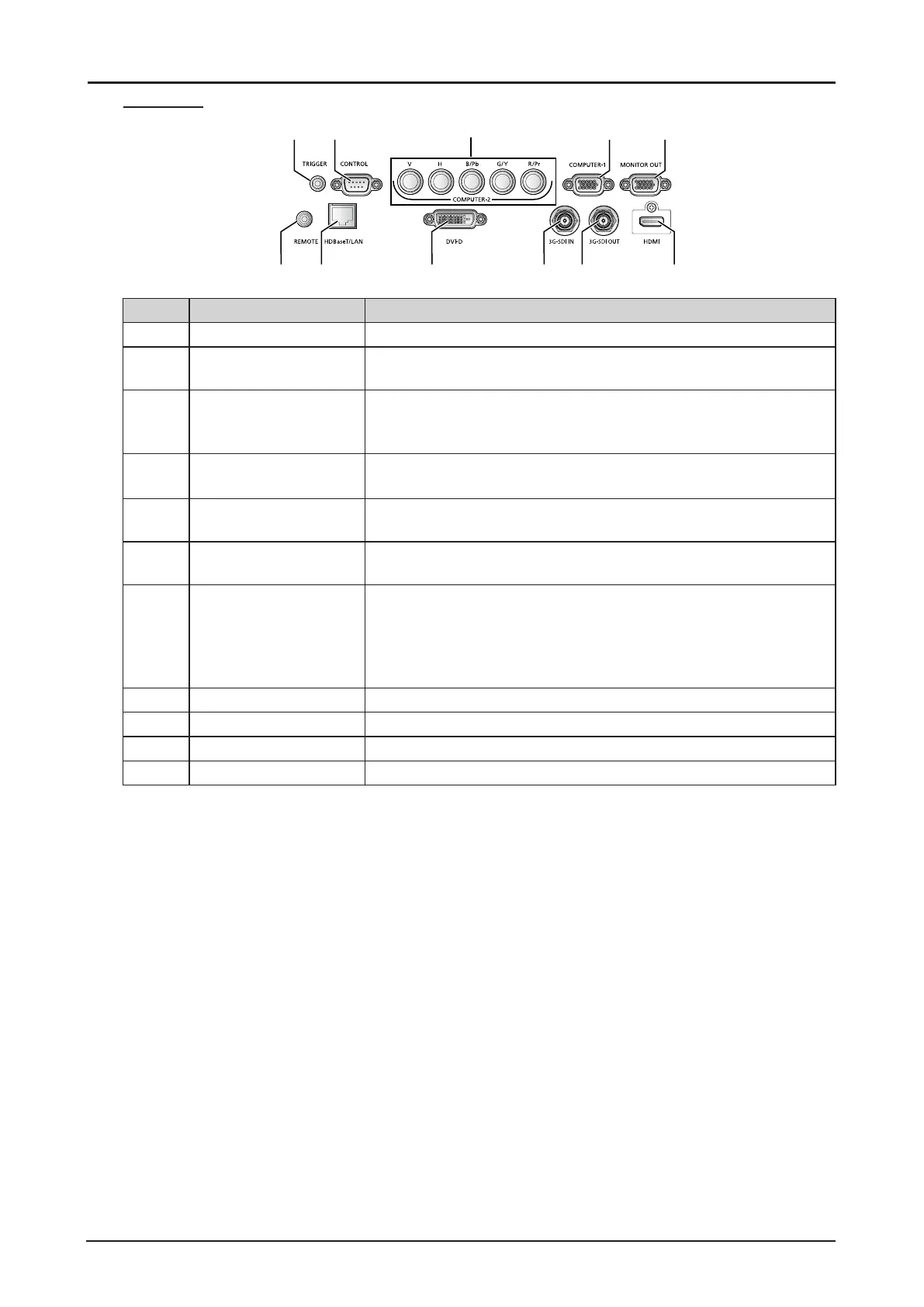
Terminals
13
5
6
87 9 10 11
Item Label Description
1 TRIGGER Provide 12V (+/- 1.5) output for screen operation.
2 CONTROL Connect to the PC for system maintenance , projector maintenance
and user commands.
3 COMPUTER-2 Receives the analog PC signal (Analog PC-2).
Connect BNC-type input connectors to the RGB or YPbPr/YCbCr
output signal video equipment.
4 COMPUTER-1 Receives the analog PC signal.
Connect the D-sub 15pin input connector to the RGB output signal.
5 MONITOR-OUT Outputs an analog RGB signal (COMPUTER-1) to display an
image on an external monitor.
6 REMOTE This terminal is used to connect the optional remote control using a
cable. Connect a 3.5 mm jack from a wired remote.
7 HDBaseT/LAN* Receives HDBaseT input including digital video and audio signals.
A LAN cable (shielded twisted pair of CAT5e or higher) can be
used for video input.
Connects the LAN cable. Used to connect the projector to a
network. However, the sound does not come out of the projector.
8 DVI-D Receives digital PC signal (with DVI-D digital PC).
9 3G-SDI IN Receives SDI signal.
10 3G-SDI OUT Outputs a signal connected with SDI IN terminal.
11 HDMI Receives digital video signals (HDMI).
* Notes on HDBaseT
■ Use a shielded cable rated at CAT5e or higher.
■ Maximum transmission distance is 100 m.
However, maximum transmission distance may be shorter in some environments.
■ Do not use the LAN cable when it is coiled or bundled.
■ Inserting or removing the LAN cable during projection may cause noise.
■ Connectivity with all HDBaseT transmitters on the market is not guaranteed.
■ Some HDBaseT transmitters may not enable correct projection when used to connect source
equipment to the projector.
 Loading...