7 . ACCESSORIES AND OPTIONS
7.64
Challenger MT500B EU
On b/w screens:
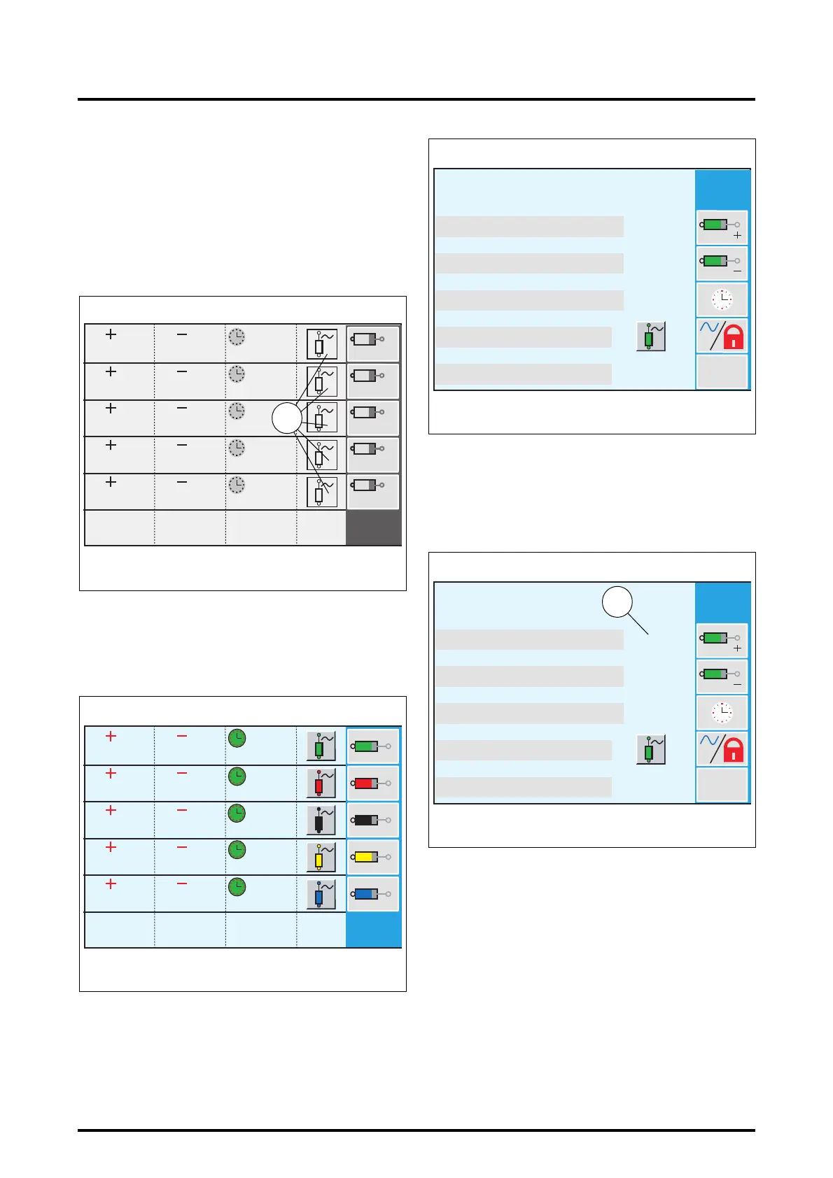
Each EHS valve is identified by a number (9 Fig. 139).
These numbers correspond to a colour on the EHS valve
controls (Fig. 138):
- 1 : green EHS valve control (Joystick)
- 2 : red EHS valve control (Joystick)
- 3 : black EHS valve control
- 4 : yellow EHS valve control
- 5 : blue EHS valve control
7.12.3 - Setting hydraulic spool valve parameters
7.12.3.1 - Setting flow rates (Fig. 140)
• Select the spool valve to adjust using keys
«
1
to «
5
.
Example: key
«
1
provides access to the first spool valve. A
new window is displayed (Fig. 141).
• Select the rod extension flow rate by pressing the
key
«
2
. The percent flow rate is displayed in red (10 Fig.
142).
NOTE: On b/w screens, this value is displayed in
reverse video.
• Adjust the flow rate value (from 0 to 100%) by rotating
the encoder.
• Validate the selected value by either pressing the
encoder, or by pressing key
«
2
. The value is displayed in
black (11 Fig. 143).
100%
100%
100%
100%
100%
100%
100%
100%
100%
100%
0s
0s
0s
0s
0s
1
5
4
3
2
1
5
4
3
2
Z3A-1361-12-04
Fig. 139
9
100%
100%
100%
100%
100%
100%
100%
100%
100%
100%
0s
0s
0s
0s
0s
Z3A-876-08-04
Fig. 140
100%
100%
0s
Reset
0s
0 < . . < 100%
0 < . . < 100%
0 < . . < 60s / >>
100%-0s-FLOAT=OK
FLOAT : OK-KO
Z3A-885-08-04
Fig. 141
100%
100%
0s
Reset
0s
0 < . . < 100%
0 < . . < 100%
0 < . . < 60s / >>
100%-0s-FLOAT=OK
FLOAT : OK-KO
Z3A-887-08-04
Fig. 142
10
 Loading...