3-8
Cisco 7600 Series Router SIP, SSC, and SPA Hardware Installation Guide
OL-5052-08
Chapter 3 Overview: Cisco 7600 Series Router Shared Port Adapters
8-Port Channelized T1/E1 SPA Overview
8-Port Channelized T1/E1 SPA Overview
The following sections describe the 8-Port Channelized T1/E1 SPA:
• 8-Port Channelized T1/E1 SPA LEDs, page 3-8
• 8-Port Channelized T1/E1 SPA Interface Specifications, page 3-9
• 8-Port Channelized T1/E1 SPA Cables, Connectors, and Pinouts, page 3-9
8-Port Channelized T1/E1 SPA LEDs
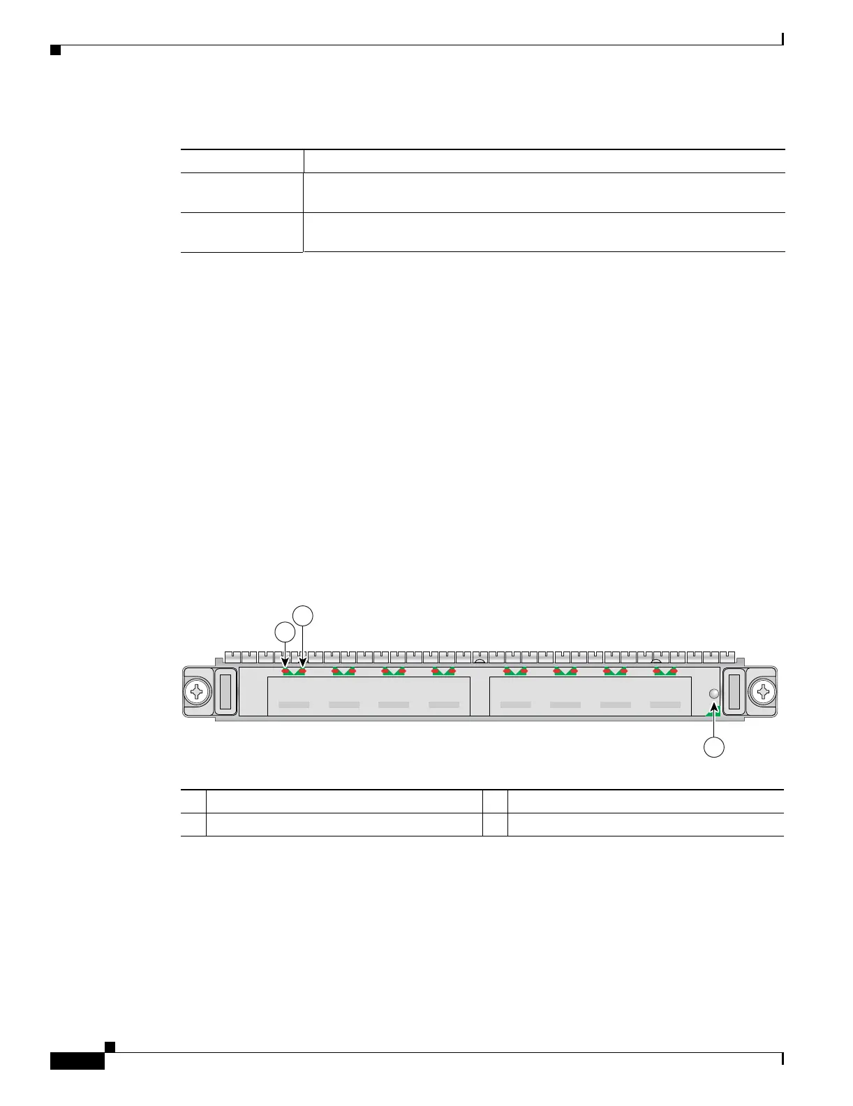
The 8-Port Channelized T1/E1 SPA has three types of LEDs. There are two LEDs for each port on the
SPA, and one STATUS LED as shown in Figure 3-3.
Figure 3-3 8-Port Channelized T1/E1 SPA Faceplate
The 8-Port Channelized T1/E1 SPA LEDs are described in Table 3-6.
Table 3-5 2-Port and 4-Port Clear Channel T3/E3 SPA Connectors
Connector Label Meaning
TX Transmitted signals appear on the center contact, and the outer shield is ground
for the 75-ohm RG-59 coaxial cable you attach to the TX BNC connector.
RX Received signals appear on the center contact, and the outer shield is ground for
the 75-ohm RG-59 coaxial cable you attach to the RX BNC connector.
1 C/A (Carrier/Alarm) LED 3 STATUS LED
2 A/L (Active Loopback) LED
STATUS
3
116852
SPA-8XCHT1/E1
C/A A/L
0
C/A
3
A/L A/L A/LC/A
2
C/A
1
C/A A/L
4
C/A
7
A/L A/L A/LC/A
6
C/A
5
1
2

 Loading...