3-61
Cisco 7600 Series Router SIP, SSC, and SPA Hardware Installation Guide
OL-5052-08
Chapter 3 Overview: Cisco 7600 Series Router Shared Port Adapters
24-Port Channelized T1/E1 ATM CEoP SPA Overview
• 24-Port Channelized T1/E1 ATM CEoP SPA Patch Panel
24-Port Channelized T1/E1 ATM CEoP SPA LEDs
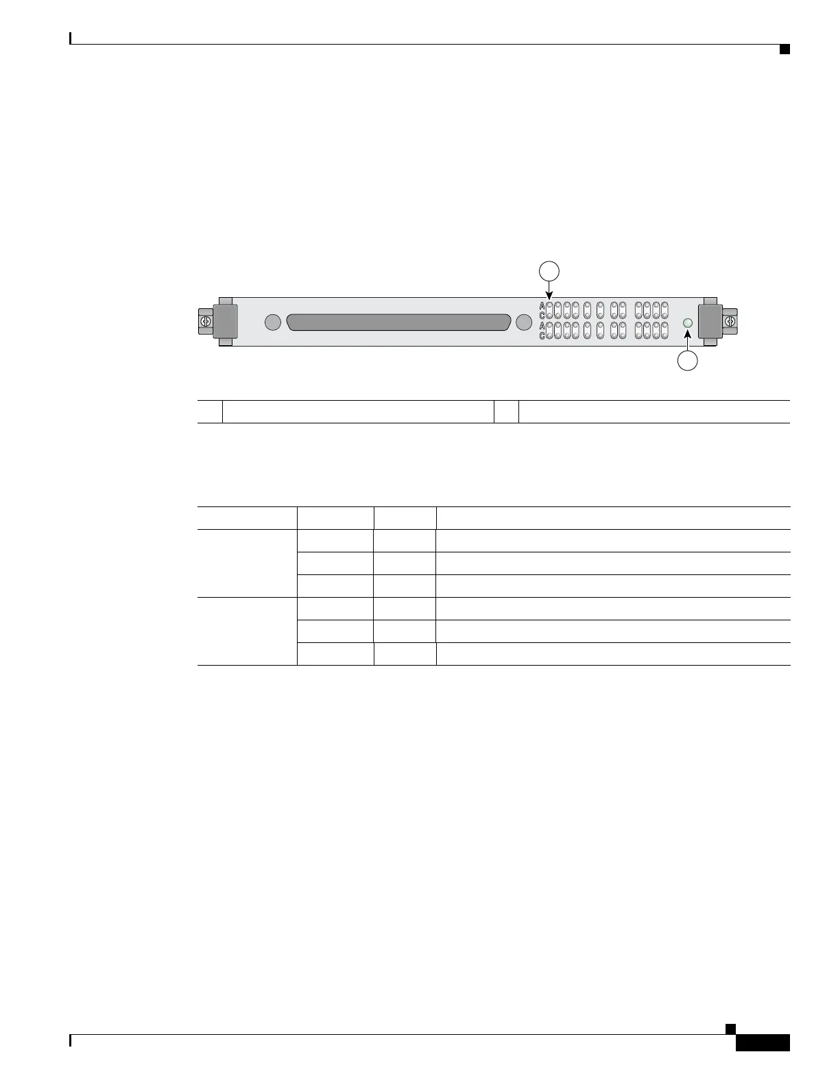
The 24-Port Channelized T1/E1 ATM CEoP SPA has two types of LEDS, as shown in this figure:
Figure 3-42 24-Port Channelized T1/E1 ATM CEoP SPA Faceplate
The 24-Port Channelized T1/E1 ATM CEoP SPA LEDs are described in the following table.
24-Port Channelized T1/E1 ATM CEoP SPA Interface Specifications
The physical layer interface for the 24-Port Channelized T1/E1 ATM CEoP SPA is a customer-installed
high-density connector. The high-density connector has thumbscrews which should be screwed into the
SPA when the cable is installed.
24-Port Channelized T1/E1 ATM CEoP SPA Cables and Connectors
The 24-Port Channelized T1/E1 ATM CEoP SPA requires a Cisco cable (part number CABLE-24T1E1J1),
which is shown in the following figure.
1 A/C (Alarm/Carrier) LED 2 STATUS LED
230030
STATUS
TX/RX
1312 14 15 16 191817 20 21 22 23
21034 765891011
SPA-24CHT1
CE-ATM
1
2
Table 3-40 24-Port Channelized T1/E1 ATM CEoP SPA LEDs
LED Label Color State Meaning
STATUS Off Off SPA power is off.
Amber On SPA power is on and good, and SPA is being configured.
Green On SPA is ready and operational.
A/C Off Off Port is not enabled by software.
Green On Port is enabled by software.
Amber On Port is enabled by software, and there is at least one alarm.

 Loading...