3-62
Cisco 7600 Series Router SIP, SSC, and SPA Hardware Installation Guide
OL-5052-08
Chapter 3 Overview: Cisco 7600 Series Router Shared Port Adapters
24-Port Channelized T1/E1 ATM CEoP SPA Overview
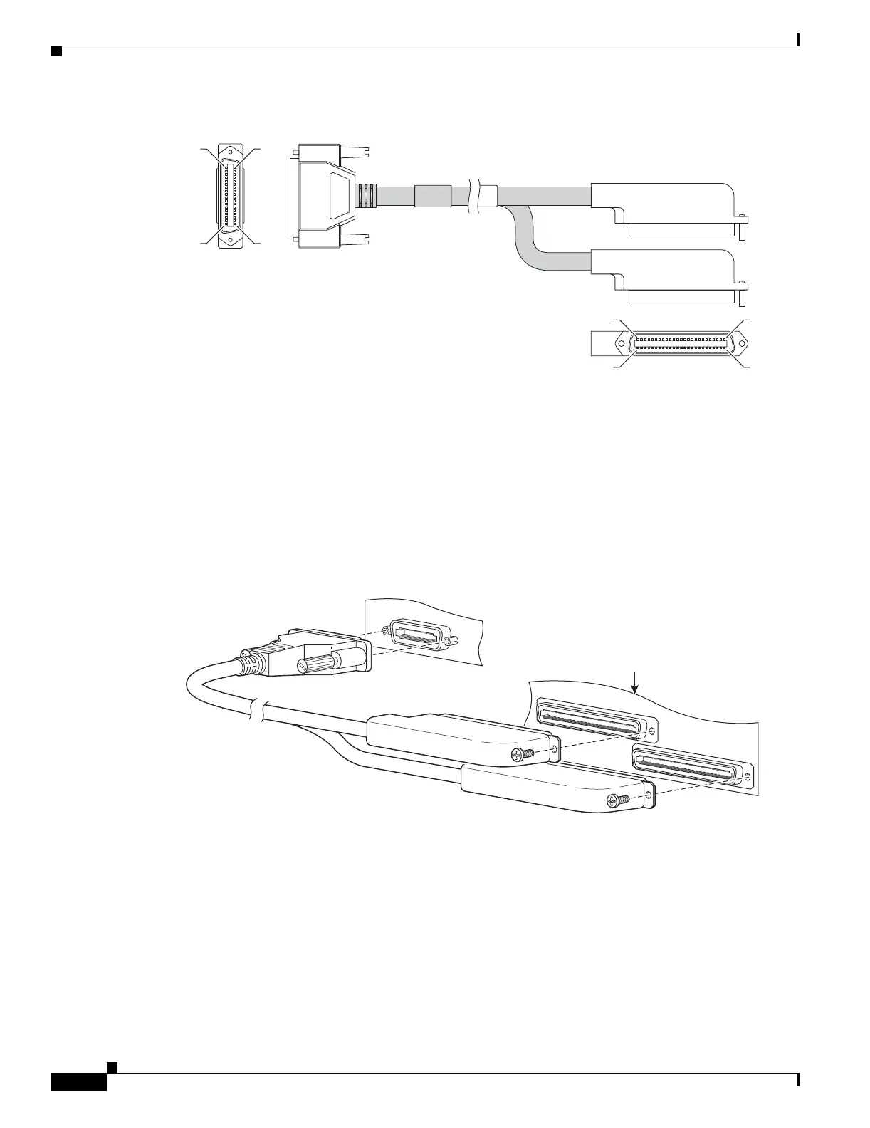
Figure 3-43 24-Port Channelized T1/E1 ATM CEoP SPA High-Density Cable
Cable Installation
One end of the cable has a 100-pin connector that plugs into the front of the 24-Port Channelized T1/E1
ATM CEoP SPA. Use the thumbscrews on either side of the connector to secure the cable to the SPA.
The other end of the cable has two 50-pin Telco connectors that attach to the rear of a 24-port RJ-45
patch panel. Both connectors are identical: one is for Transmit (TX) and the other is for Receive (RX).
The following figure shows how the cable is connected between the 24-Port Channelized T1/E1 ATM
CEoP SPA and the patch panel.
Figure 3-44 Cable Installation between SPA and Patch Panel
SPA Cable Pinouts
The following table shows the cable pinouts for the cable (part number CABLE-24T1E1J1) that is
installed between the 24-Port Channelized T1/E1 ATM CEoP SPA and the rear of the patch panel.
511
10050
26
1
50
25
250106
SPA-24CHT1-CE-ATM
TRANSMIT
RECEIVE
250107
24-Port Patch Panel
(rear view, rotated
180
o
for clarity)

 Loading...