6-24
Cisco PIX Firewall Hardware Installation Guide
78-15170-01
Chapter 6 PIX 525
Installing a DC Power Supply
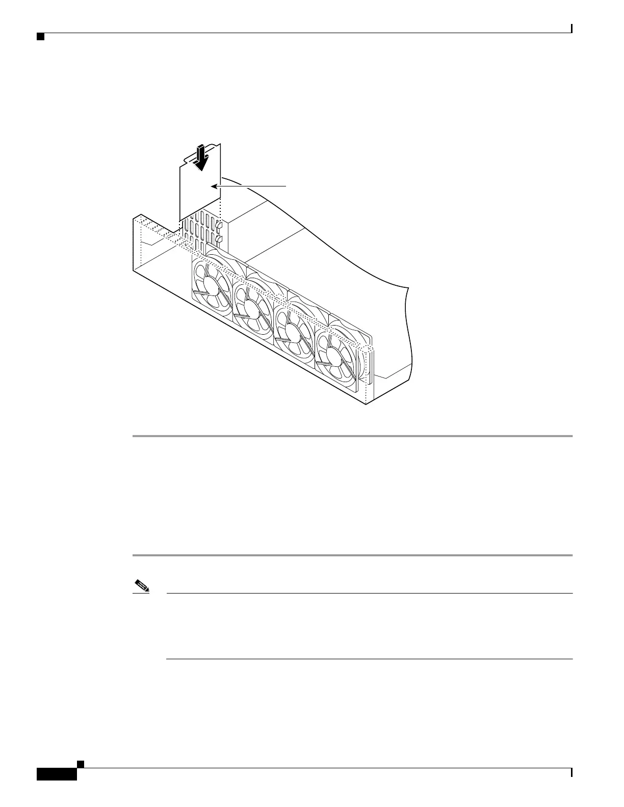
Step 10 Replace the air separator as shown in Figure 6-24, holding all cables to the right of the separator as you
slip it into the chassis.
Figure 6-24 Replacing the Air Separator
Step 11 Replace the chassis cover as described in “Replacing the Chassis Cover.”
Rerouting the Fan Wiring
If the fan wiring in your router is not routed on top of the fans, you need to reroute the fan wiring. This
will make future power supply replacement easier.
Complete these steps to reroute the fan wiring:
Step 1 Pull the fan closest to the power supply away from the sheet metal tabs. (See Figure 6-25.)
Note To help with reconnecting the cables, write down which colored cable connects to which fan.
See Table 6-4 for a list of the wire colors. There are three different lengths of two-wire ± 12 VDC
power cables. The two shortest cables go to the two fans that you will remove in Step 9. The two
longer cables go to the two remaining fans you will remove in Step 10 and Step 11. The
remaining cable goes to the power connector on the backplane. These cables are color-coded.
Front panel
52021
Air separator
 Loading...