4-12
Cisco PIX Firewall Hardware Installation Guide
78-15170-01
Chapter 4 PIX 515/515E
Removing and Replacing the PIX 515/515E Chassis Cover
Step 6 Power the primary unit on first, then power on the secondary unit. Within a few seconds, the active unit
automatically downloads its configuration to the standby unit.
If the primary unit fails, the secondary unit automatically becomes active.
Removing and Replacing the PIX 515/515E Chassis Cover
This section describes how to remove and replace the chassis cover from the PIX 515/515E. This section
includes the following topics:
• Removing the Chassis Cover, page 4-12
• Replacing the Chassis Cover, page 4-13
Removing the Chassis Cover
Complete the following to remove the chassis cover:
Note Removing the PIX Firewall case does not affect your Cisco warranty. Upgrading the PIX Firewall does
not require any special tools and does not create any radio frequency leaks.
Step 1 Read the Regulatory Compliance and Safety Information for the Cisco PIX Firewall document.
Step 2 Unplug the power cord from the power outlet. Ensure that the PIX 515/515E is powered off. Once the
upgrade is complete, you can safely reconnect the power cord.
Warning
Before working on a system that has an On/Off switch, turn OFF the power and unplug the power cord.
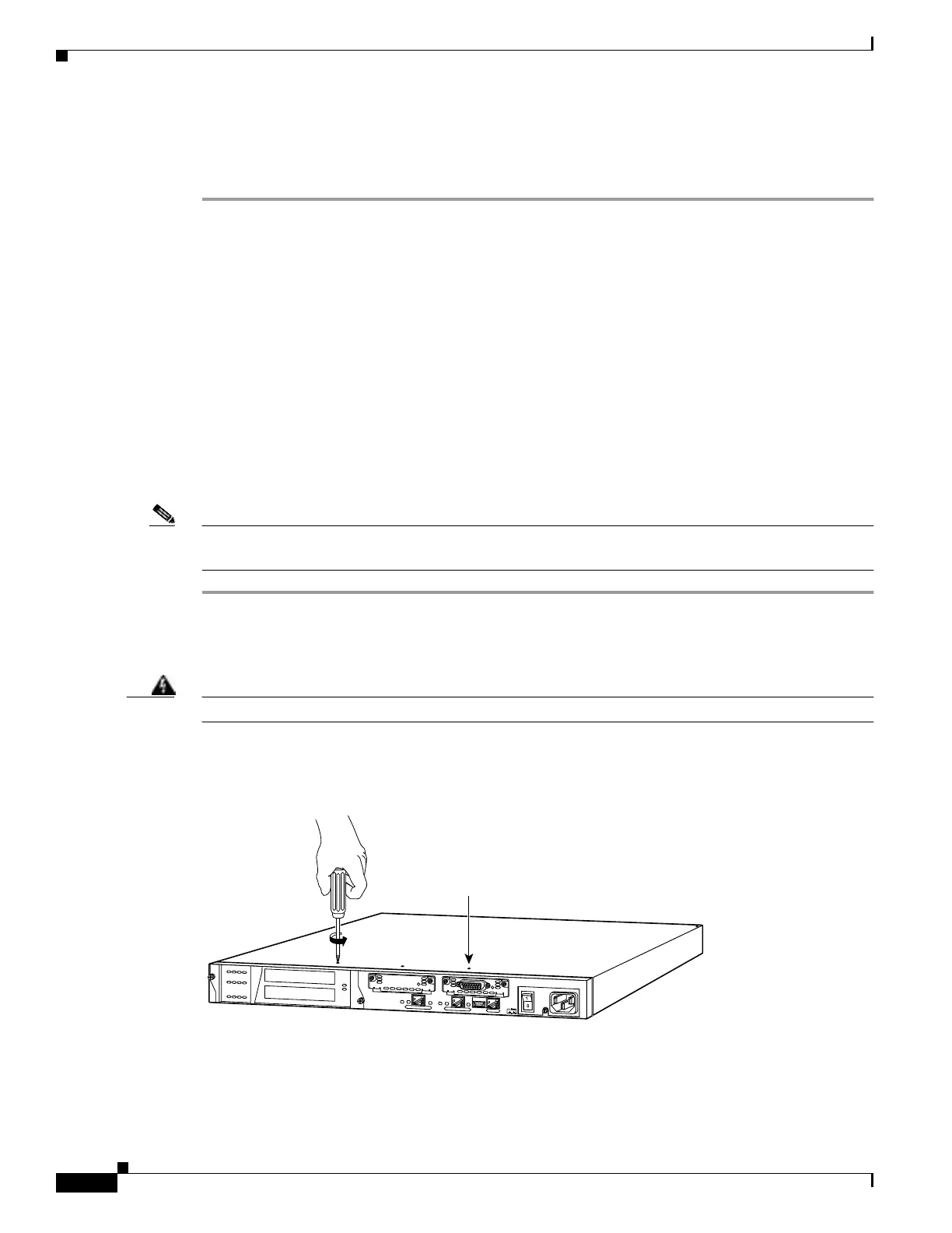
Step 3 Remove the screws from the front of the chassis on the PIX 515/515E (Figure 4-13).
Figure 4-13 Removing PIX 515/515E Top Panel Screws
Step 4 With the front of the unit facing you, push the top panel back by about one inch as shown in Figure 4-14.
24305
D
O
N
O
T
I
N
S
T
A
L
L
I
N
T
E
R
F
A
C
E
C
A
R
D
S
W
I
T
H
P
O
W
E
R
A
P
P
L
I
E
D
C
O
N
S
O
L
E
1
0
/1
0
0
E
T
H
E
R
N
E
T
0
/0
L
in
k
F
D
X
F
D
X
1
0
0
M
b
p
s
L
in
k
1
0
0
M
b
p
s
F
A
I
L
O
V
E
R
1
0
/1
0
0
E
T
H
E
R
N
E
T
0
/
0
PIX-515
Top panel screws (4)
 Loading...