3-5
Cisco PIX Firewall Hardware Installation Guide
78-15170-01
Chapter 3 PIX 506/506E
Connecting a Power Supply Module to the PIX 506/506E
Step 3 Connect the inside network cable to the interface connector marked ETHERNET 0 or ETHERNET 1.
Note The inside or outside network connections can be made to either interface port on the
PIX 506/506E.
Step 4 Connect the outside network cable to the remaining Ethernet port.
Connecting a Power Supply Module to the PIX 506/506E
This section describes how to connect the power supply module to the PIX 506/506E. Use this
information in conjunction with the appropriate version of the Regulatory Compliance and Safety
Information for the Cisco PIX Firewall document, that shipped with your unit.
The PIX 506/506E uses an external AC to DC power supply. Power is supplied to the PIX 506/506E by
connecting the power supply to the back of the PIX 506/506E and connecting a separate AC power cord
to the power supply.
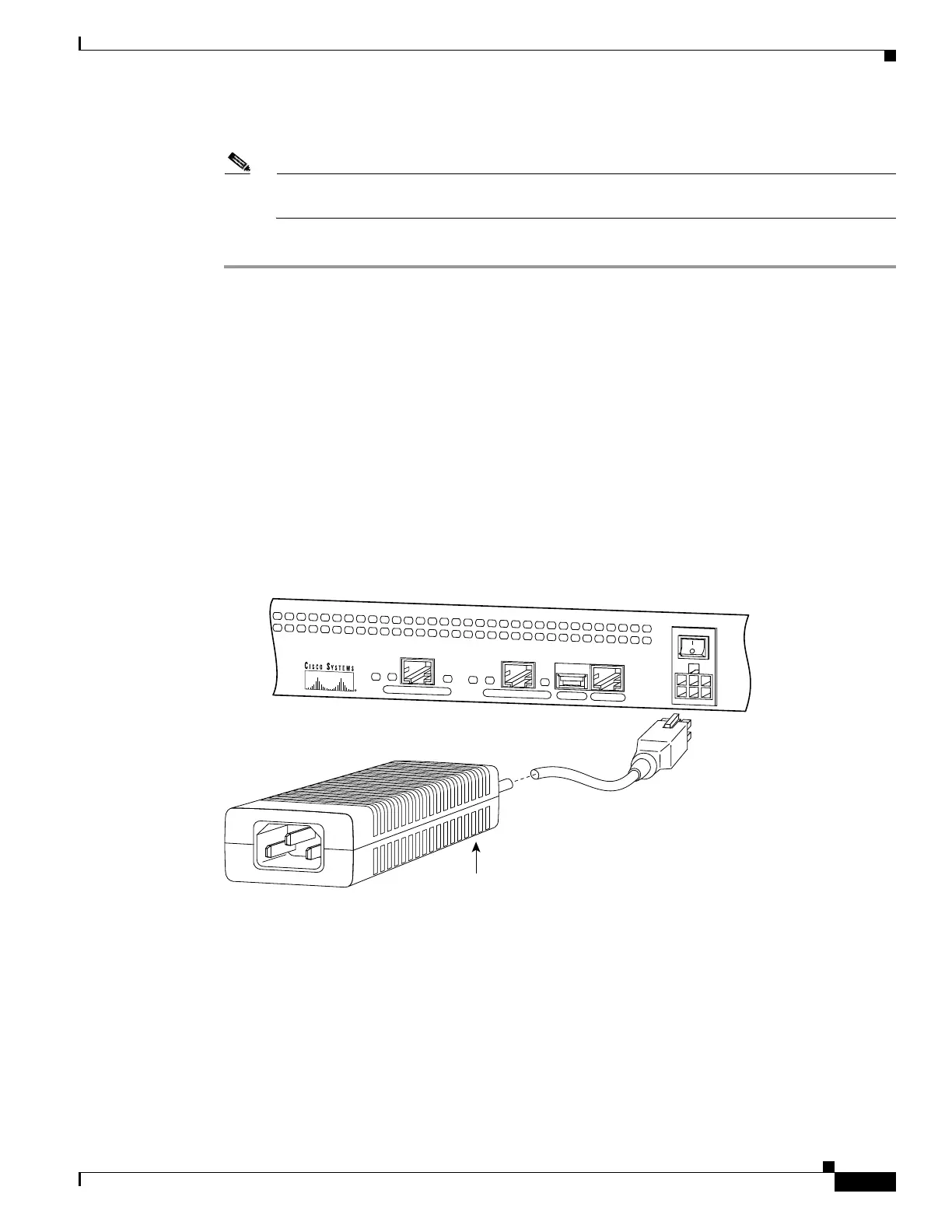
Figure 3-9 displays the cable connection from the power supply to the PIX 506, and displays the AC
power cord connector (at the opposite end of the power supply).
Figure 3-8 Connecting the Power Supply Module to the PIX 506 6- Pin Connector
C
O
N
S
O
L
E
E
T
H
E
R
N
E
T
0
ACT
LINK
LINK
DC
POWER
INPUT
ACT
U
S
B
E
T
H
E
R
N
E
T
1
38854
Power supply
 Loading...