4-11
Cisco PIX Firewall Hardware Installation Guide
78-15170-01
Chapter 4 PIX 515/515E
Installing LAN-Based Failover
Installing LAN-Based Failover
LAN-based failover supports failover between two units connected over a dedicated Ethernet interface.
LAN-based failover eliminates the need for a special failover cable and overcomes the distance
limitations imposed by the failover cable.
Note Both PIX Firewall units must be the same model number, have the same amount of RAM, Flash memory,
number and type of interfaces, and be running the same software version.
Complete the following to set up a LAN-based failover connection:
Step 1 Disconnect both the PIX Firewall units, so that there is no traffic flow between them. If the Failover cable
is connected to the PIX Firewall, disconnect it.
Step 2 Configure the PIX Firewall units. For information on configuring the PIX Firewall, refer to “Configuring
LAN-Based Failover,” section in Chapter 10 “Using PIX Firewall Failover” in the Cisco PIX Firewall and
VPN Configuration Guide.
Step 3 Power off both the units.
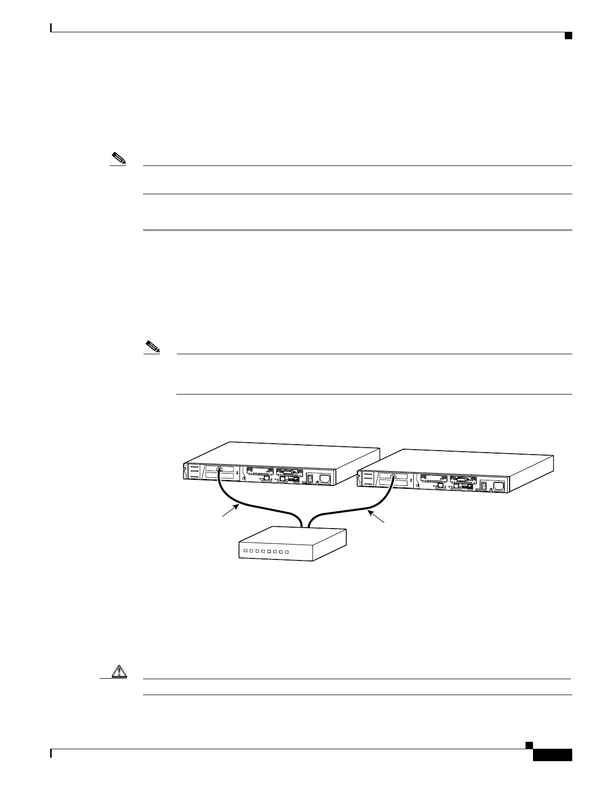
Step 4 Connect the LAN Failover interfaces to the dedicated switch/hub, as shown in Figure 4-12.
Note A dedicated LAN interface and a dedicated switch (or VLAN) is required to implement
LAN-based failover. You cannot use a crossover Ethernet cable to connect the two PIX Firewall
units.
Figure 4-12 LAN- Based Failover Connections
Step 5
If you are using Stateful Failover, use one of the following types of connections, that is appropriate for
your system, between the dedicated interfaces on the PIX Firewall units:
• Cat 5 crossover cable directly connecting the primary unit to the secondary unit.
• 100BaseTX full duplex on a dedicated switch or dedicated VLAN of a switch.
• 1000BaseTX full duplex on a dedicated switch or dedicated VLAN of a switch.
Caution Do not turn the power on until the units are connected and the primary unit is configured completely.
D
O
N
O
T
I
N
S
T
A
L
L
I
N
T
E
R
F
A
C
E
C
A
R
D
S
W
I
T
H
P
O
W
E
R
A
P
P
L
I
E
D
C
O
N
S
O
L
E
1
0
/
1
0
0
E
T
H
E
R
N
E
T
0
L
in
k
F
D
X
F
D
X
1
0
0
M
b
p
s
L
i
n
k
1
0
0
M
b
p
s
F
A
IL
O
V
E
R
1
0
/
1
0
0
E
T
H
E
R
N
E
T
1
PIX-515
D
O
N
O
T
I
N
S
T
A
L
L
I
N
T
E
R
F
A
C
E
C
A
R
D
S
W
I
T
H
P
O
W
E
R
A
P
P
L
I
E
D
C
O
N
S
O
L
E
1
0
/
1
0
0
E
T
H
E
R
N
E
T
0
L
in
k
F
D
X
F
D
X
1
0
0
M
b
p
s
L
in
k
1
0
0
M
b
p
s
F
A
IL
O
V
E
R
1
0
/
1
0
0
E
T
H
E
R
N
E
T
1
PIX-515
87313
PIX 515
PIX 515
Dedicated Ethernet
interface
Hub/switch
Dedicated Ethernet
interface
 Loading...