4-4
Cisco PIX Firewall Hardware Installation Guide
78-15170-01
Chapter 4 PIX 515/515E
Installing the PIX 515/515E
Surface Mounting the PIX 515/515E
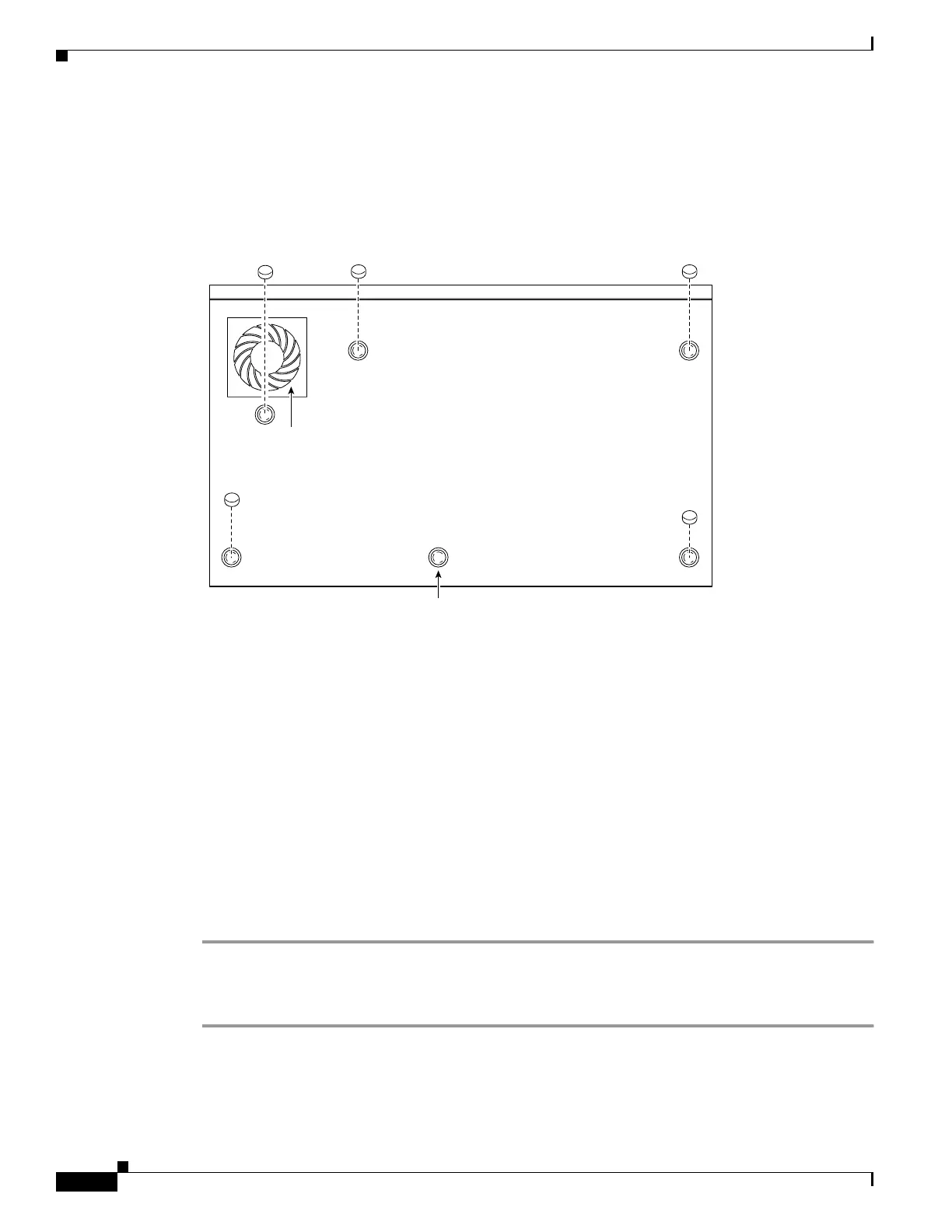
If you do not want to rack mount the unit, attach the rubber feet to the bottom of the unit as shown in
Figure 4-5.
Figure 4-5 Attaching the Rubber Feet to the PIX 515/515E
Rack Mounting the PIX 515/515E
Observe the following before installing the PIX 515/515E into an equipment rack:
• To install optional circuit boards or memory, install the brackets on the unit for rack mounting, but
do not put the PIX 515/515E in the equipment rack before installing the new boards. The chassis
cover of the PIX 515/515E must be removed to properly install or remove a circuit board. Refer to
“Removing and Replacing the PIX 515/515E Chassis Cover” for information on how to remove and
replace the chassis cover.
–
If you need information on installing a circuit board, refer to “Installing a Circuit Board in the
PIX 515/515E”.
–
If you need to install additional memory, refer to “Installing a Memory Upgrade”.
Complete the following to install the PIX 515/515E in a rack:
Step 1 Attach the bracket to the unit using the supplied screws. You can attach the brackets to the holes near the
front of the unit.
Step 2 Attach the unit to the equipment rack.
Fan
Unused
24301
 Loading...