6-11
Cisco PIX Firewall Hardware Installation Guide
78-15170-01
Chapter 6 PIX 525
Removing and Replacing the PIX 525 Chassis Cover
Replacing the Chassis Cover
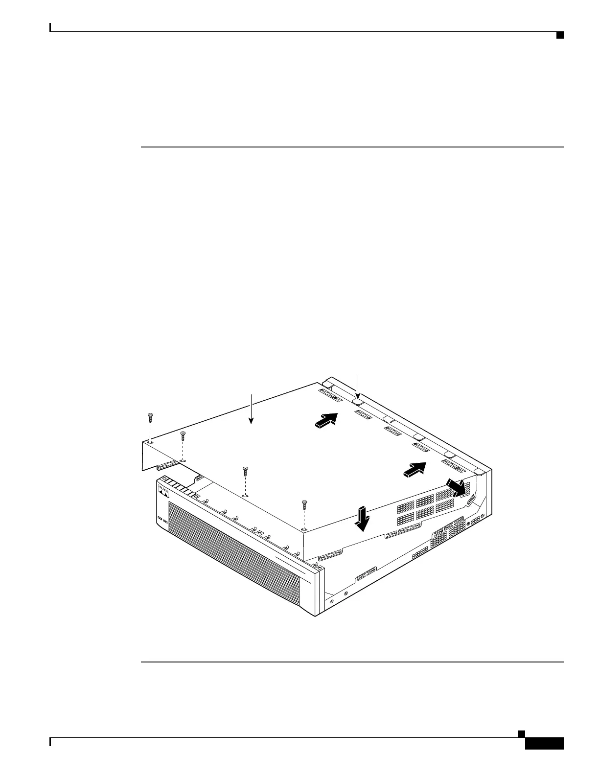
This section describes replacing the chassis cover on the PIX 525.
Complete these steps to remove the chassis cover:
Step 1 Place the chassis bottom so that the front panel is facing you.
Step 2 Hold the chassis cover over the chassis bottom, and align each of the cover tabs with the chassis tabs at
the top rear of the chassis. (See Figure 6-10.)
Step 3 Lower the front of the top cover to close the chassis, and ensure the following:
• The chassis cover tabs fit under the edge of the chassis rear panel so that they are not exposed.
• The chassis tabs fit under the chassis cover so that they are not exposed.
• The chassis cover side tabs on both sides fit inside the chassis side panels so that they are not
exposed.
When the chassis cover is properly assembled, no tabs are visible.
Step 4 Secure the chassis cover with four screws.
Step 5 Reinstall all interface cables.
Figure 6-10 Replacing the Chassis Cover
Step 6
Connect the power to the site power and power on the PIX 525. The internal power supply fan should go
on.
Chassis bottom
Front panel
Chassis cover
55330
Chassis
tabs
C
I
S
C
O
S
E
C
U
R
I
T
Y
P
I
X
5
2
5
S
E
R
I
E
S
F
IR
E
W
A
L
L
P
O
W
E
R
A
C
T
I
V
E
 Loading...