4-2
Cisco PIX Firewall Hardware Installation Guide
78-15170-01
Chapter 4 PIX 515/515E
PIX 515/515E Product Overview
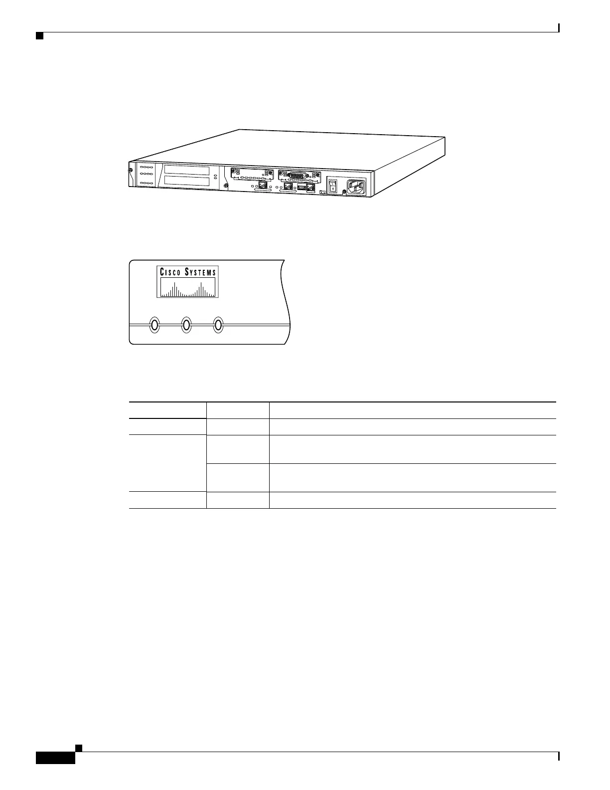
Figure 4-2 shows the rear view of the PIX 515/515E.
Figure 4-2 PIX 515/515E Rear Panel
Figure 4-3 shows the PIX 515/515E front panel LEDs.
Figure 4-3 PIX 515/515E Front Panel LEDs
Table 4-1 lists the state of the PIX 515/515E front panel LEDs.
67850
D
O
N
O
T
I
N
S
T
A
L
L
I
N
T
E
R
F
A
C
E
C
A
R
D
S
W
I
T
H
P
O
W
E
R
A
P
P
L
I
E
D
C
O
N
S
O
L
E
1
0
/
1
0
0
E
T
H
E
R
N
E
T
0
/
0
L
in
k
F
D
X
F
D
X
1
0
0
M
b
p
s
L
in
k
1
0
0
M
b
p
s
F
A
I
L
O
V
E
R
1
0
/
1
0
0
E
T
H
E
R
N
E
T
0
/0
PIX-515
POWER ACT NETWORK
25735
Table 4-1 PIX 515/515E Front Panel LEDs
LED State Description
POWER On On when the unit has power.
ACT On On when the unit is the active failover unit. If failover is present, the
light is on when the unit is the active unit.
Off Off when the unit is in standby mode. If failover is not enabled, this
light is off.
NETWORK On On when at least one network interface is passing traffic.
 Loading...