4-9
Cisco PIX Firewall Hardware Installation Guide
78-15170-01
Chapter 4 PIX 515/515E
Installing Failover
Installing Failover
Complete the following steps to install a failover connection:
Step 1 Power off both the primary and secondary units.
Note Both PIX Firewall units has to be the same model number, have at least as much RAM, have the
same Flash memory size, and be running the same software version.
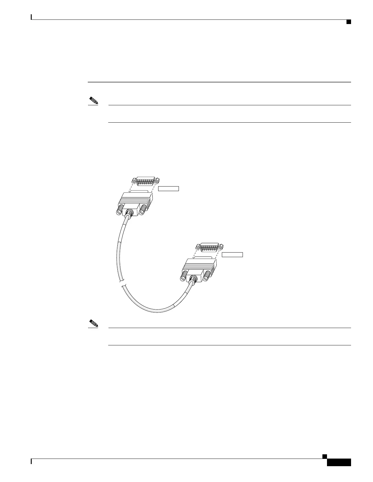
Step 2 Locate the failover cable (shown in Figure 4-10). This cable is shipped separately from the PIX Firewall
unit. The cable is labeled Primary on one end and Secondary on the other.
Install the cable for the PIX 515/515E as shown in Figure 4-10.
Figure 4-10 PIX 515/515E Failover Cable Connection
Note You can connect the PIX 515 unit to the PIX 515 unit but you cannot connect the PIX 515 unit
to the PIX 515E unit or vice versa. Both units must be identical.
Step 3 Connect the Primary end of the failover cable to the first PIX Firewall unit, that is, the one you have
already configured.
Step 4 Connect the Secondary end of the failover cable to the standby unit.
Step 5 Connect a power cord to the power connector on the rear panel of each unit, and the other end of each
power cord to (preferably separate) power outlets.
24297
Secondary end
Primary end
S
E
C
O
N
D
A
R
Y
P
R
I
M
A
R
Y
FAILOVER
FAILOVER
 Loading...