4-15
Cisco PIX Firewall Hardware Installation Guide
78-15170-01
Chapter 4 PIX 515/515E
Installing a Memory Upgrade
Memory Installation Steps
Complete the following to install additional system memory:
Step 1 Remove network wires and any cords connecting to the PIX Firewall unit if the unit is rack-mounted.
The PIX 515/515E should be removed from the rack and placed on a stable working surface. Ensure that
the unit is unplugged from its power source.
Step 2 Unpack the items in the memory upgrade kit.
Remove the top panel from the PIX Firewall unit. Remove all screws holding the assembly in place.
Refer to “Removing and Replacing the PIX 515/515E Chassis Cover” for information on how to remove
and replace the top panel.
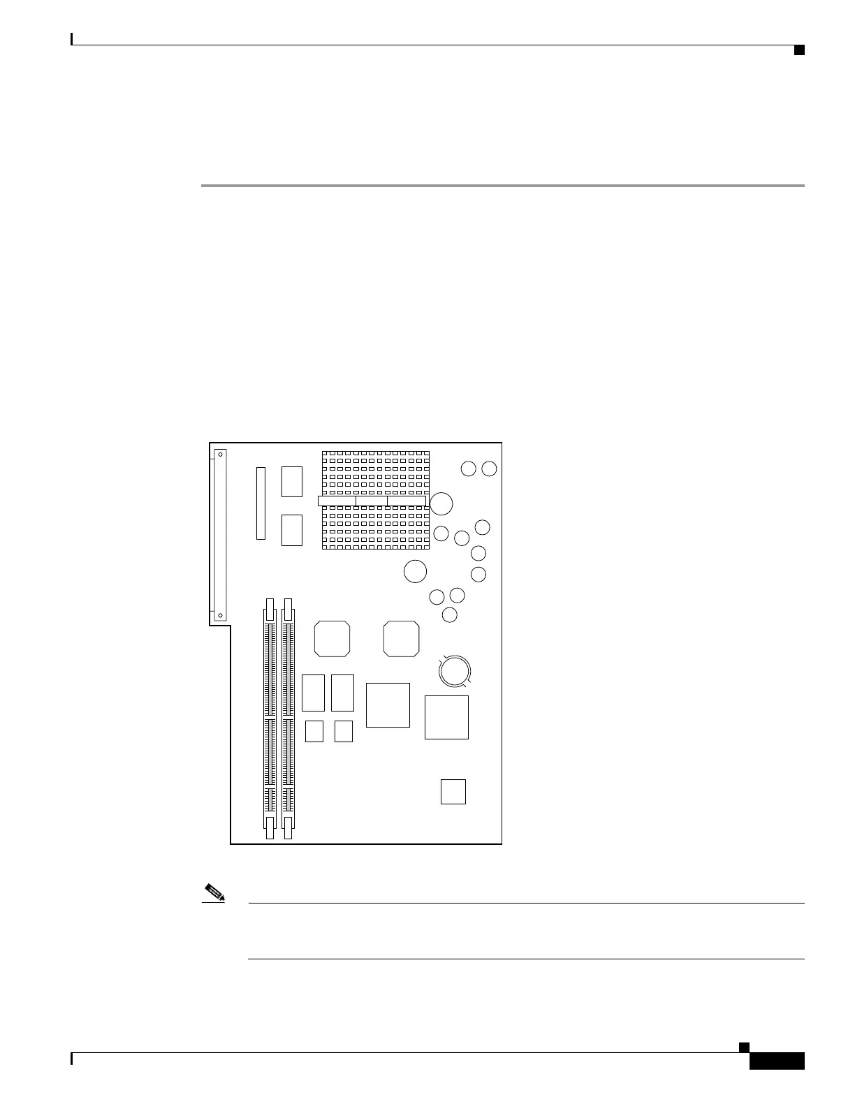
Step 3 Determine the location of your system memory sockets (See Figure 4-16).
Step 4 Use the markings on the motherboard to determine the socket numbers. Always install the first memory
board into the lowest socket number. Progressively add memory boards into higher numbered sockets.
Figure 4-16 PIX 515 System Memory Location
Note Do not install a 64 MB DIMM in the PIX 515. You will not be able to properly replace the top
panel because of the height of a 64 MB DIMM. Operating the PIX Firewall chassis without a top
panel installed may cause damage to the unit.
24302
Front
 Loading...