2-3
Cisco PIX Firewall Hardware Installation Guide
78-15170-01
Chapter 2 PIX 501
Installing the PIX 501
Installing the PIX 501
Place the PIX 501 on a flat, stable surface. The PIX 501 is not rack mountable.
Complete these steps to install the PIX 501:
Step 1 Connect Port 0, the outside Ethernet port, to the public network.
• Use the yellow Ethernet cable (72-1482-01) to connect the device to a switch or hub.
• Use the orange Ethernet cable (72-3515-01) to connect the device to a DSL modem, cable modem,
or router.
Step 2 Connect your PC or the other network devices to one of the four switched inside ports (numbered 1
through 4).
Connecting a Power Supply Module to the PIX 501
This section describes how to connect the power supply module to a PIX 501. Use this information in
conjunction with the appropriate version of the Regulatory Compliance and Safety Information for the
Cisco PIX Firewall document.
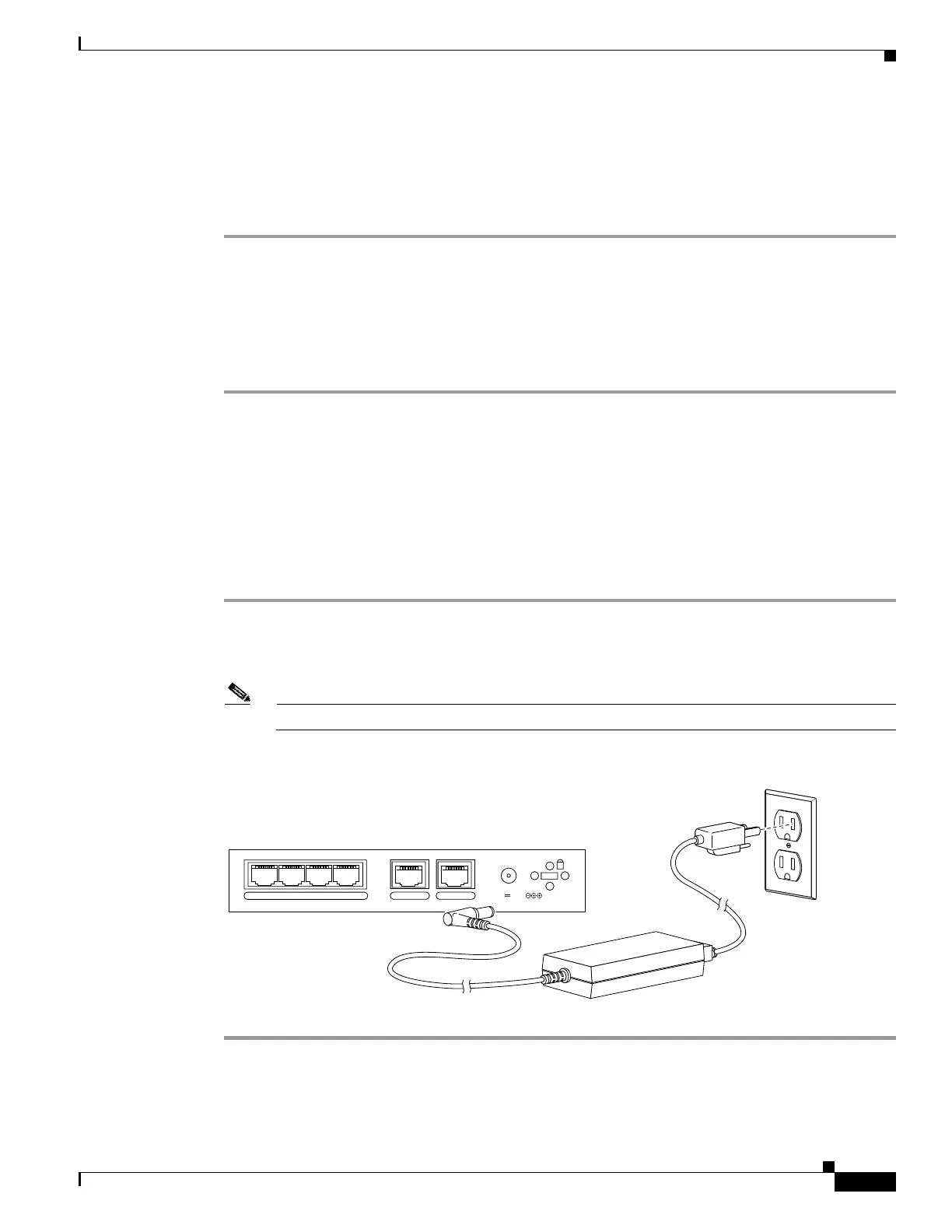
Complete these steps to connect the power supply module to the PIX 501:
Step 1 Connect the small, round connector of the power supply cable to the power connector on the rear panel.
(See Figure 2-4.)
Step 2 Connect the AC power connector of the power supply input cable to an electrical outlet.
Note The PIX 501 does not have a power switch. Completing Step 2 powers on the device.
Figure 2-4 Connecting the Power Supply Module to the PIX 501
POWER
43
2
1
0 CONSOLE
3.3V 4.5A
71534
Power supply
 Loading...