7-11
Cisco PIX Firewall Hardware Installation Guide
78-15170-01
Chapter 7 PIX 535
Installing a Memory Upgrade
Caution If you remove the PIX Firewall chassis top panel, always reinstall the top panel. Running the
PIX Firewall without the top panel may cause overheating and damage to electrical
components.
Memory Installation Steps
Complete these steps to install additional system memory:
Step 1 If the unit is rack-mounted, remove network wires and any cords connecting to the PIX Firewall unit.
Ensure that the unit is unplugged from its power source.
Step 2 Unpack the items in the memory upgrade kit.
Step 3 Remove the component tray and all the screws holding the assembly in place.
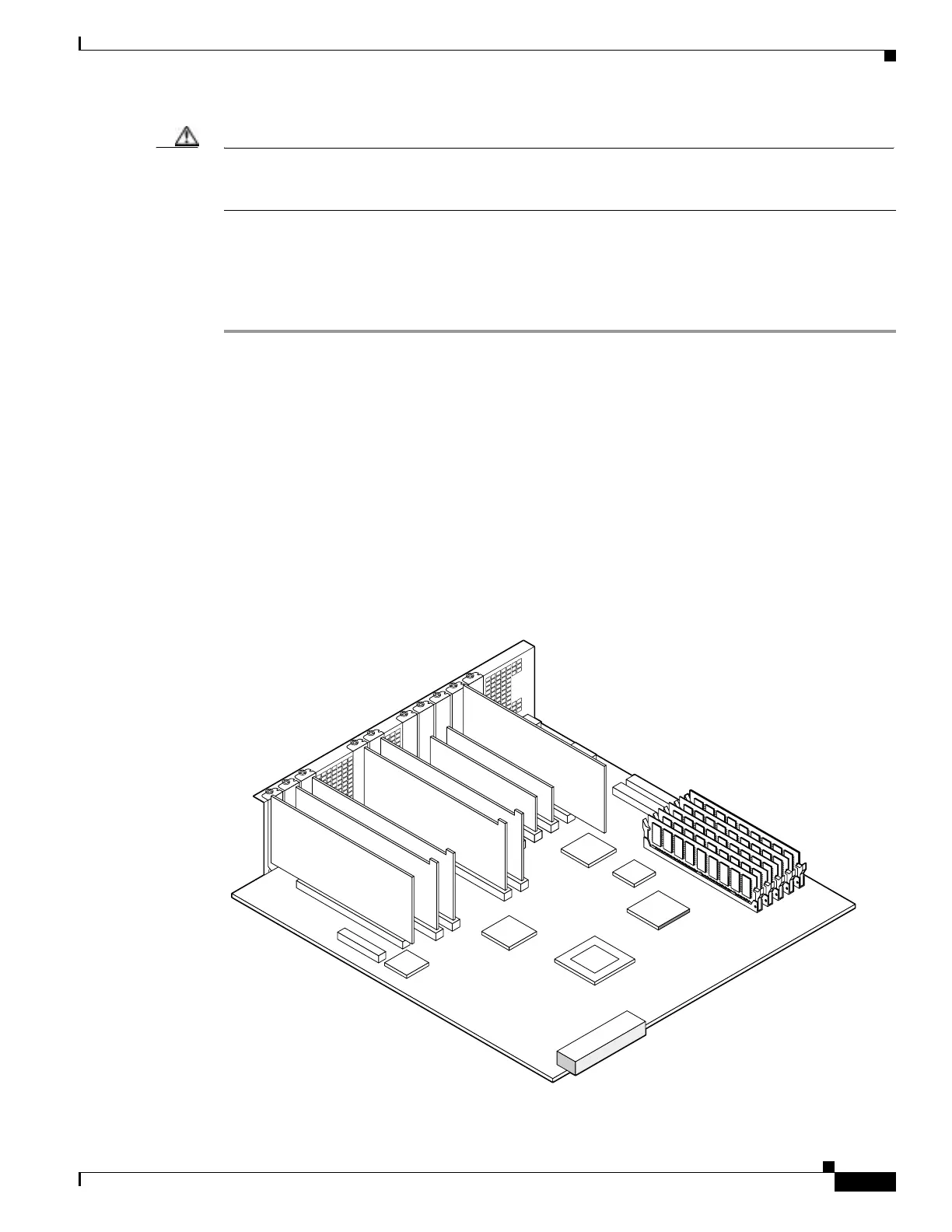
Determine the location of your system memory sockets (see Figure 7-7).
Step 4 Use the markings on the motherboard to determine the socket numbers. Always install the first memory
DIMM in J40, and the second one in J43. This constitutes Bank 0. If your PIX Firewall has 512 MB
currently installed in it, then both J40 and J43 will be filled. Install the additional 512 MB of RAM in
socket J41 and J44.
Make sure that memory from the same vendor is placed together in the same bank (J40 & J43 - Bank 0)
or (J41 & J44 - Bank 1).
Figure 7-7 System Memory Location on the PIX 535 Component Tray
61920
 Loading...