4-5
Cisco PIX Firewall Hardware Installation Guide
78-15170-01
Chapter 4 PIX 515/515E
Installing the PIX 515/515E
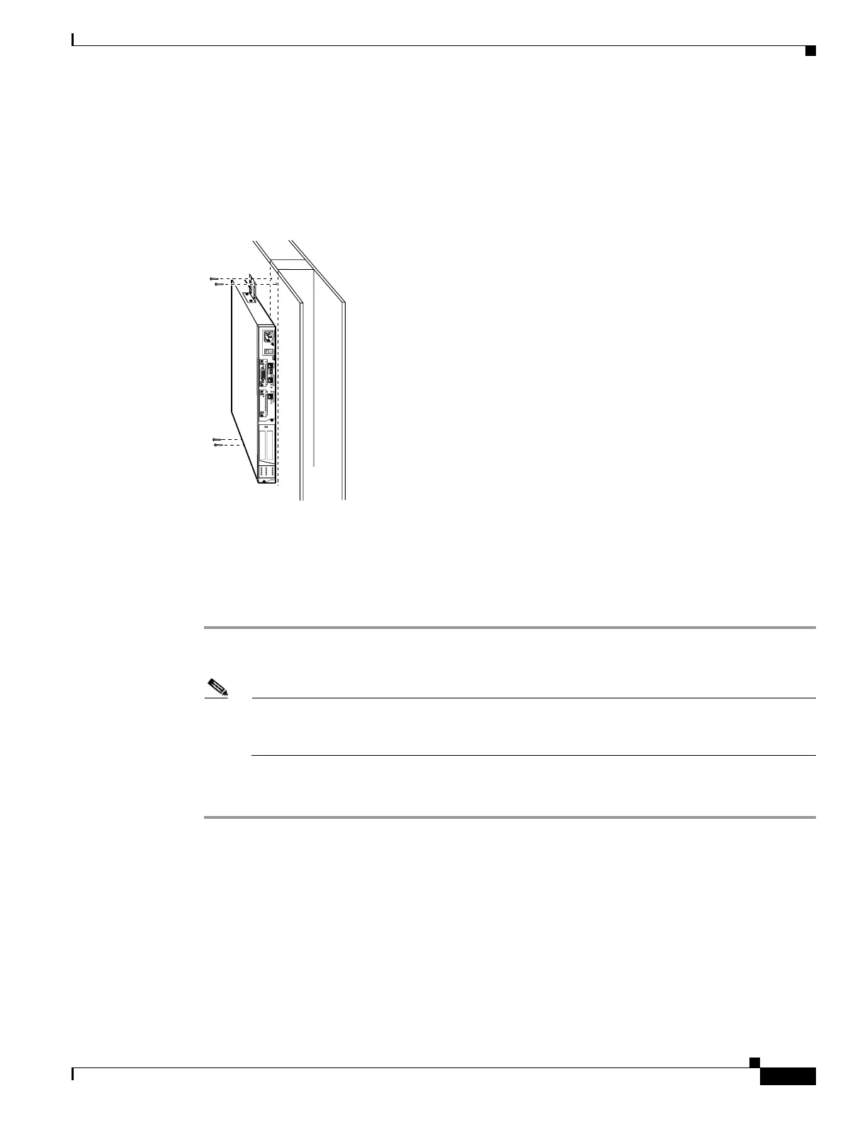
Vertical Mounting the PIX 515/515E
To mount the PIX 515/515E vertically, attach the brackets to the side of the unit and mount the unit
vertically as shown in Figure 4-6.
Figure 4-6 Installing the PIX 515/515E Vertically
Installing the PIX 515/515E
Complete the following to install the PIX 515/515E:
Step 1 Connect the cable as shown in Figure 4-7 so that you have either a DB-9 or DB-25 connector on one end
as required by the serial port for your computer, and the other end is the RJ-45 connector.
Note Use the Console port to connect to a computer to enter configuration commands. Locate the
serial cable from the accessory kit. The serial cable assembly consists of a null modem cable
with RJ-45 connectors, and one DB-9 connector and a DB-25 connector.
Step 2 Connect the RJ-45 connector to the PIX 515/515E Console port and connect the other end to the serial
port connector on your computer.
24303
D
O
N
O
T
IN
S
T
A
L
L
IN
T
E
R
F
A
C
E
C
A
R
D
S
W
IT
H
P
O
W
E
R
A
P
P
L
I
E
D
C
O
N
S
O
L
E
1
0
/
1
0
0
E
T
H
E
R
N
E
T
0
/
0
L
in
k
F
D
X
F
D
X
1
0
0
M
b
p
s
L
i
n
k
1
0
0
M
b
p
s
F
A
I
L
O
V
E
R
1
0
/
1
0
0
E
T
H
E
R
N
E
T
0
/
0
PIX-515
 Loading...