Step 7 Click OK and then click Apply.
Networks
Virtual Access Points (VAPs), segment the wireless LAN into multiple broadcast domains that are wireless
equivalent of the Ethernet VLANs. VAPs simulate multiple access points on one physical WAP device. Up
to four VAPs are supported on this Cisco WAP device.
Each VAP can be independently enabled or disabled, with the exception of VAP0. The VAP0 is the physical
radio interface and remains enabled as long as the radio is enabled. To disable the VAP0, the radio itself must
be disabled.
Each VAP is identified by a user-configured Service Set Identifier (SSID). Multiple VAPs cannot have the
same SSID name. SSID broadcasts can be enabled or disabled independently on each VAP. SSID broadcast
is enabled by default.
SSID Naming Conventions
The default SSID for VAP0 is ciscosb. Every additional VAP created has a blank SSID name. The SSIDs for
all VAPs can be configured to other values. The SSID can be any alphanumeric, case-sensitive entry from 2
to 32 characters.
The following characters are allowed:
• ASCII 0x20 through 0x7E.
• Trailing and leading spaces (ASCII 0x20) are not permitted.
This means that spaces are allowed within the SSID, but not as the first or last character including the period
“.” (ASCII 0x2E).
Note
VLAN IDs
Each VAP is associated with a VLAN, and is identified by a VLAN ID (VID). A VID can be any value from
1 to 4094, inclusive. The WAP150/361 device supports 33 active VLANs (32 for WLAN plus one management
VLAN).
By default, the VID assigned to the configuration utility for the WAP device is 1, which is also the default
untagged VID. If the management VID is the same as the VID assigned to a VAP, then the WLAN clients
associated with this specific VAP can administer the WAP device. If needed, an access control list (ACL)
can be created to disable administration from WLAN clients.
Configuring VAPs
To configure VAPs:
Step 1 Select Wireless > Networks.
Step 2 In the Radio field, click the radio interface (Radio 1 or Radio 2) to which the VAP configuration parameters are applied.
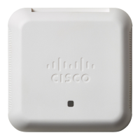
Cisco WAP150 Wireless-AC/N Dual Radio Access Point with PoE / Cisco WAP361 Wireless-AC/N Dual Radio Wall Plate Access Point with PoE
52
Wireless
Networks
 Loading...
