SiBE121123_A Check
Service Diagnosis 206
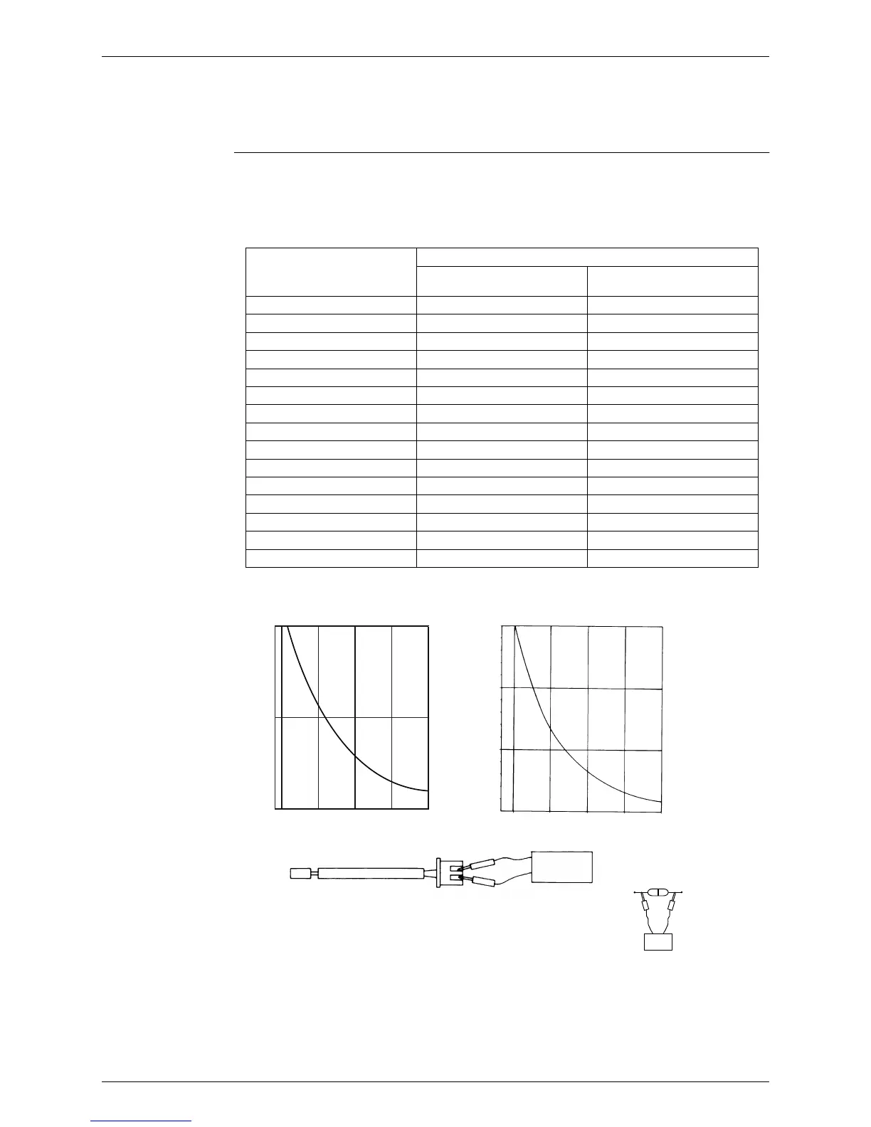
8. Check
8.1 Thermistor Resistance Check
Check No.01 Disconnect the connectors of the thermistors from the PCB, and measure the resistance of
each thermistor using a tester.
The relationship between normal temperature and resistance is shown in the table and the
graphs below.
When the room temperature thermistor is directly mounted on a PCB, remove the PCB from
the control PCB to measure the resistance.
When the connector of indoor heat exchanger thermistor is soldered on the PCB, remove
the thermistor and measure the resistance.
Thermistor temperature (°C)
Resistance (kΩ)
Room temperature thermistor
for FTX and ATX series
Other thermistors
–20 73.4 197.8
–15 57.0 148.2
–10 44.7 112.1
–5 35.3 85.60
0 28.2 65.93
5 22.6 51.14
10 18.3 39.99
15 14.8 31.52
20 12.1 25.02
25 10.0 20.00
30 8.2 16.10
35 6.9 13.04
40 5.8 10.62
45 4.9 8.707
50 4.1 7.176
(R25°C = 10 kΩ, B = 3435 K) (R25°C = 20 kΩ, B = 3950 K)
(R11952)
Other thermistorsRoom temperature thermistor
for FTX and ATX series
(˚C)(˚C)
50
25
0
–15
0
15 30
45
(kΩ)
(kΩ)
–15
0
15 30
45
150
100
50
Tester
(R17417)
Room temperature
thermistor
Tester
Resistance range
(R18296)
 Loading...