Indoor Unit SiBE121123_A
43 Printed Circuit Board Connector Wiring Diagram
1.8 FDXS25/35EAVMB, FDXS25/35E7VMB, FDXS50CVMB,
FDXS50C7VMB
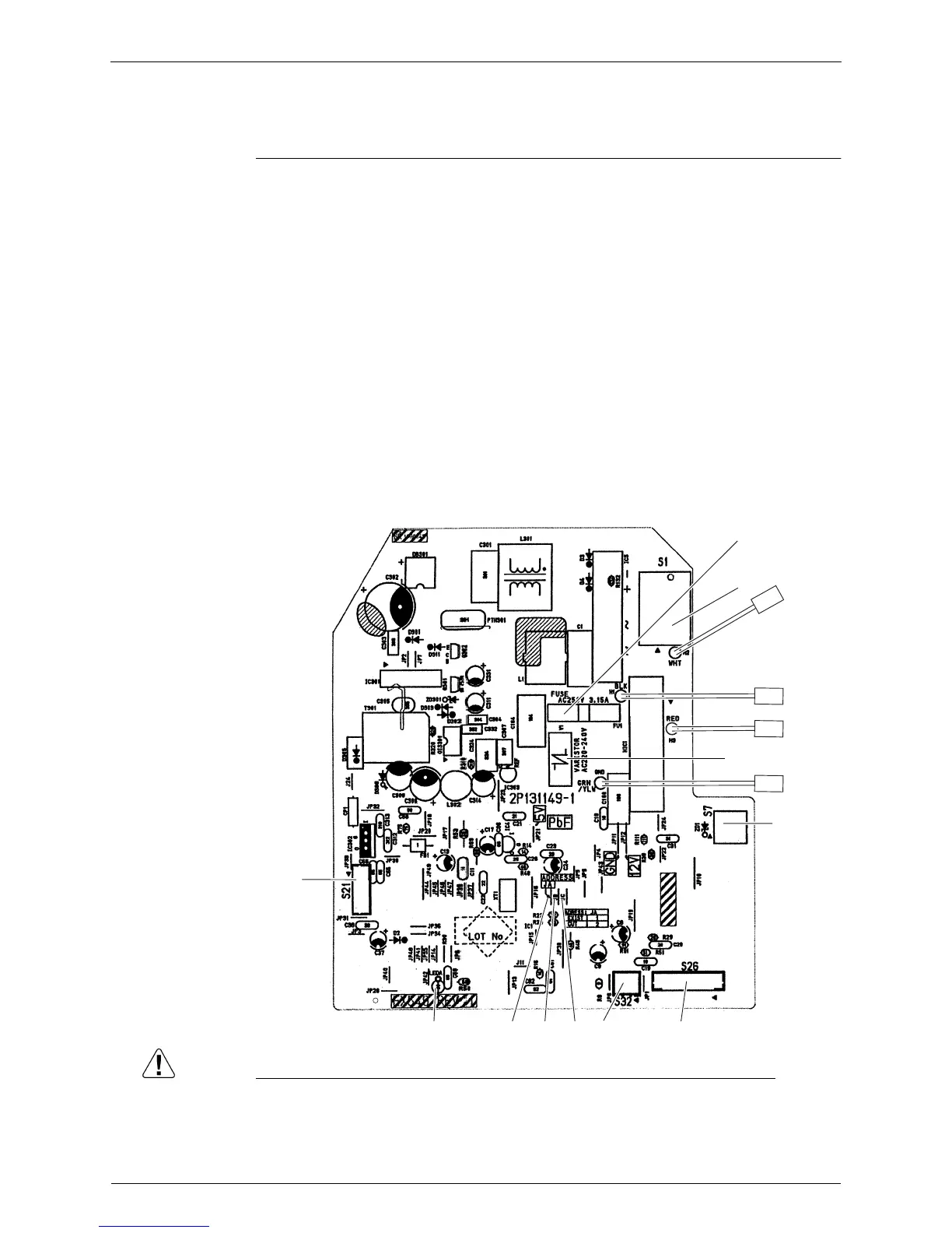
Control PCB
Caution Replace the PCB if you accidentally cut the jumpers other than JA, JB and JC.
Jumpers are necessary for electronic circuit. Improper operation may occur if you cut any of
them.
1) S1 Connector for AC fan motor
2) S7 Connector for AC fan motor (Hall IC)
3) S21 Connector for centralized control (HA)
4) S26 Connector for display PCB
5) S32 Connector for indoor heat exchanger thermistor
6) H1, H2, H3 Connector for terminal board
7) GND Connector for terminal board (earth)
8) JA Address setting jumper
∗ Refer to page 226 for detail.
9) JB Fan speed setting when compressor stops for thermostat OFF
JC Power failure recovery function (auto-restart)
∗ Refer to page 230 for detail.
10) LED A LED for service monitor (green)
11) FU1 (F1U) Fuse (3.15A, 250V)
12) V1 (V1TR) Varistor
S1
H2
S7
S26
S32
JCJBJA
S21
2P131149-1
LED A
FU1
H1
H3
V1
GND
 Loading...