Indoor Unit SiBE121123_A
29 Printed Circuit Board Connector Wiring Diagram
1. Indoor Unit
1.1 FTXG25/35/50JV1BW(S)(A)
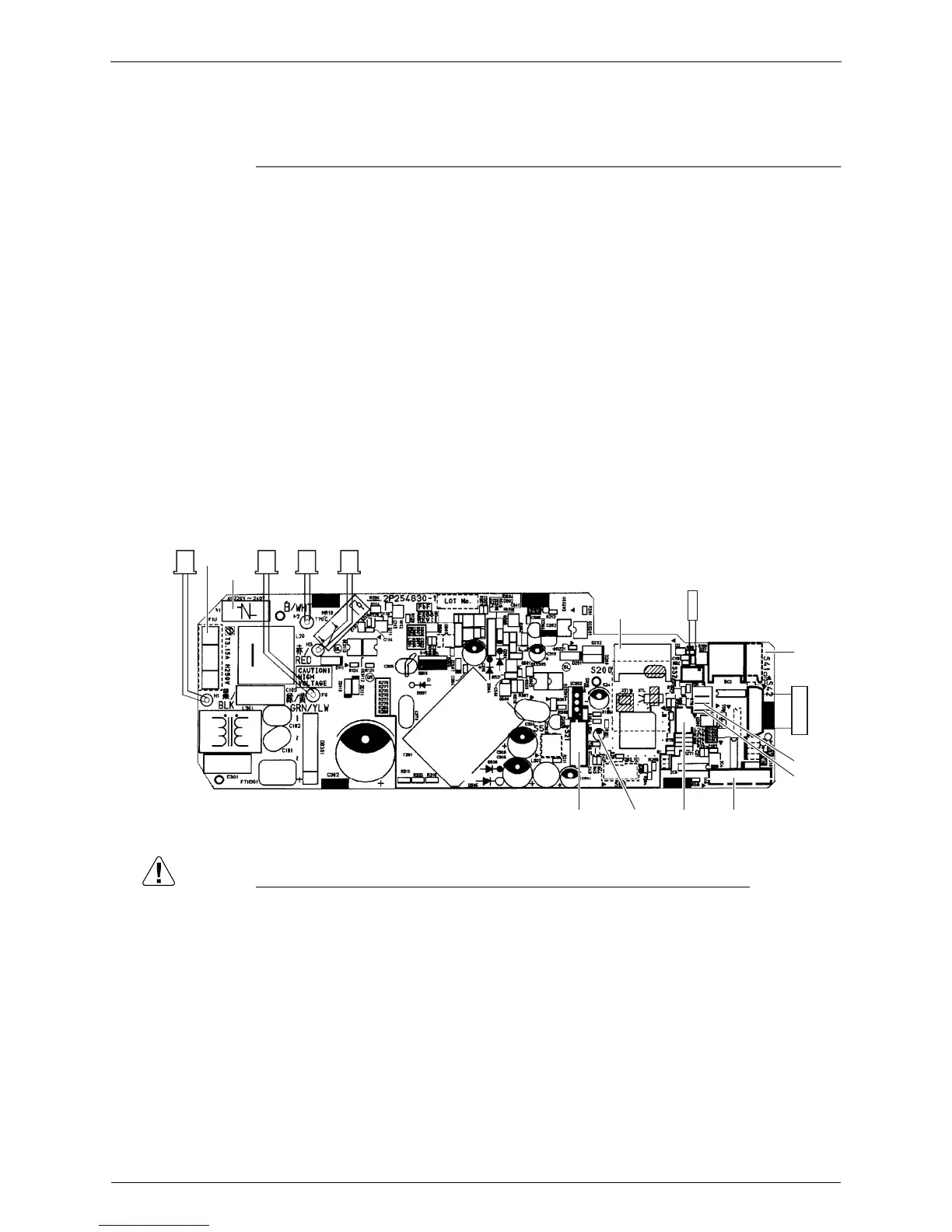
Control PCB
Caution Replace the PCB if you accidentally cut the jumpers other than JB and JC.
Jumpers are necessary for electronic circuit. Improper operation may occur if you cut any of
them.
1) S21 Connector for centralized control (HA)
2) S25 Connector for INTELLIGENT EYE sensor PCB
3) S32 Indoor heat exchanger thermistor
4) S41 Connector for swing motors
5) S42 Connector for reduction motor (front panel mechanism) and limit switch
6) S46 Connector for signal receiver / display PCB
7) S200 Connector for fan motor
8) H1, H2, H3,
FG
Connector for terminal board
9) JB Fan speed setting when compressor stops for thermostat OFF
JC Power failure recovery function (auto-restart)
∗ Refer to page 230 for detail.
10) LED A LED for service monitor (green)
11) F1U Fuse (3.15 A, 250 V)
12) V1 Varistor
S42
S41
S32
JB
JC
S200
H3H2FG
S46
S21 S25
LED A
V1
F1U
H1
2P254830-1
 Loading...