Check SiBE121123_A
217 Service Diagnosis
8.15 Power Module Check
Check No.22
Note: Check to make sure that the voltage between (+) and (–) of the power module (IPM1) is approx.
0 V before checking.
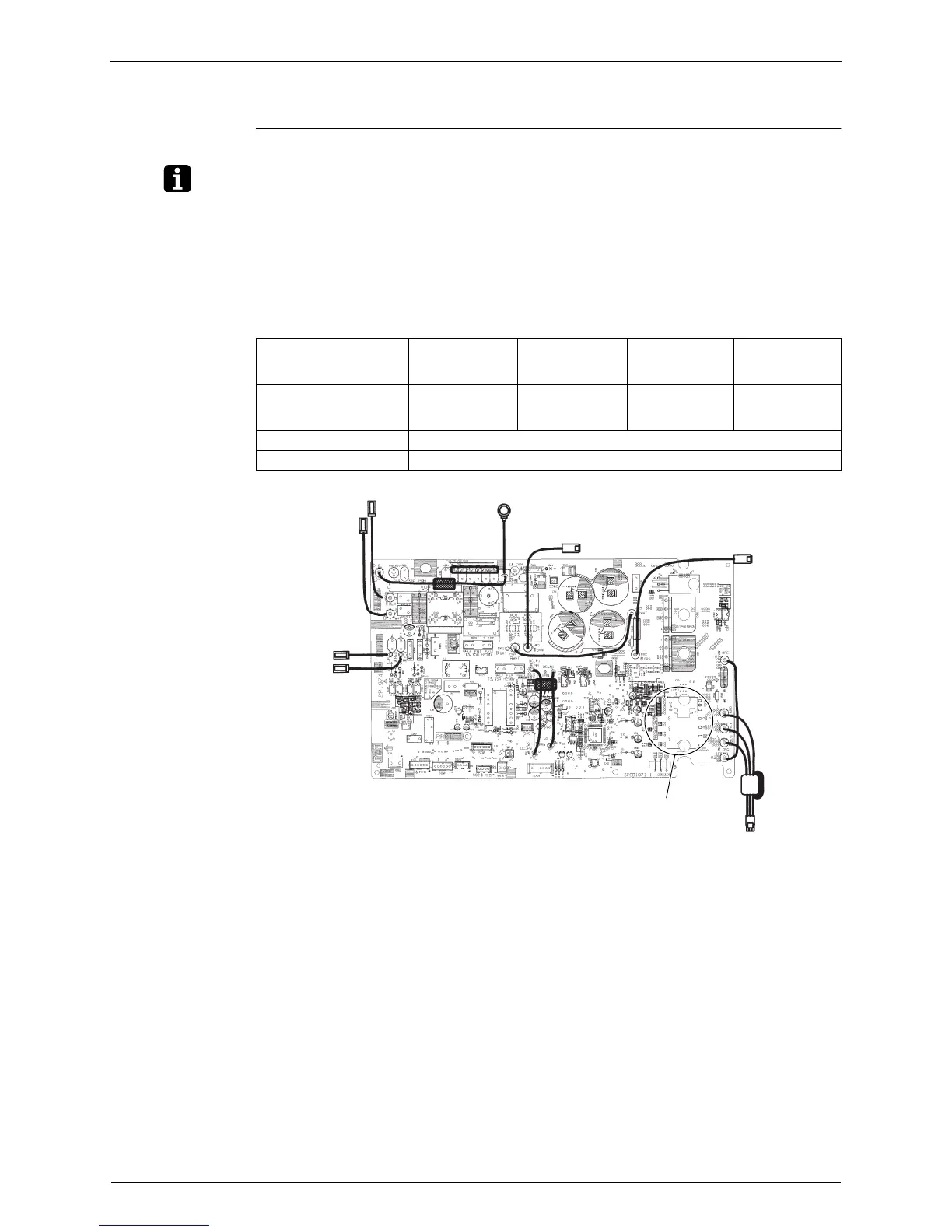
Disconnect the compressor harness connector from the outdoor unit PCB. To disengage the
connector, press the protrusion on the connector.
Follow the procedure below to measure resistance between the terminals of the power
module and the terminals of the compressor with a multi-tester. Evaluate the measurement
results for a judgment.
The illustration is for 50 class model as representative.
Negative (–) terminal of
tester (positive terminal
(+) for digital tester)
Power module
(+)
UVW Power module
(–)
UVW
Positive (+) terminal of
tester (negative terminal
(–) for digital tester)
UVW Power module
(+)
UVW Power module
(–)
Resistance is OK. several kΩ ~ several MΩ
Resistance is NG. 0 Ω or ∞
(R18388)
Power module
 Loading...