Indoor Unit SiBE121123_A
35 Printed Circuit Board Connector Wiring Diagram
1.4 FTX20/25/35JV1B, FTX20/25/35J2V1B, ATX20/25/35JV1B,
ATX20/25/35J2V1B
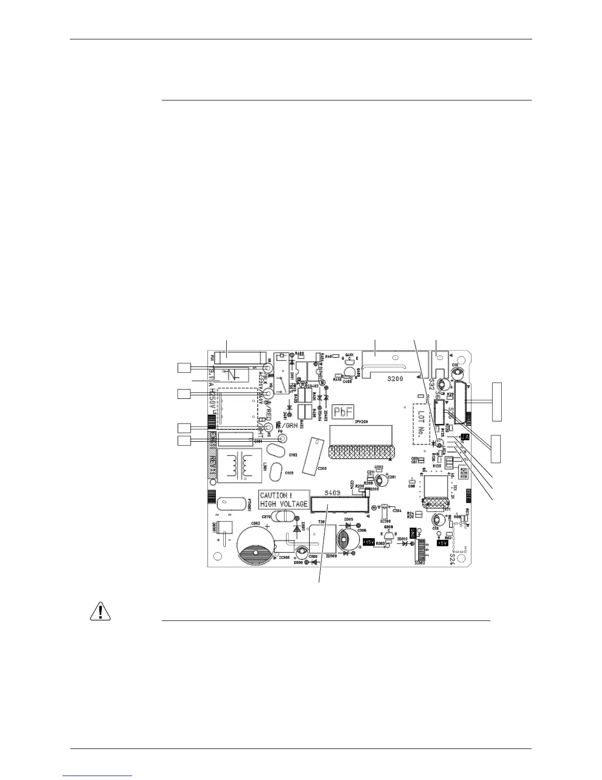
Control PCB
Caution Replace the PCB if you accidentally cut the jumpers other than JA, JB and JC.
Jumpers are necessary for electronic circuit. Improper operation may occur if you cut any of
them.
1) S6 Connector for swing motor (horizontal blade)
2) S26 Connector for display PCB
3) S32 Connector for indoor heat exchanger thermistor
4) S200 Connector for fan motor
5) S403 Connector for adaptor PCB (option)
6) H1, H2, H3,
FG
Connector for terminal board
7) V1 Varistor
8) JA Address setting jumper
∗ Refer to page 226 for detail.
9) JB Fan speed setting when compressor stops for thermostat OFF
JC Power failure recovery function (auto-restart)
∗ Refer to page 230 for detail.
10) LED A LED for service monitor (green)
11) FU1 (F1U) Fuse (3.15 A, 250 V)
FU1
H1
H3
V1
H2
FG
S200 LED A S32
S26
S6
JA
JC
JB
S403
2P206569-1
 Loading...