Indoor Unit SiBE121123_A
41 Printed Circuit Board Connector Wiring Diagram
1.7 FLXS25/35/50BAVMB
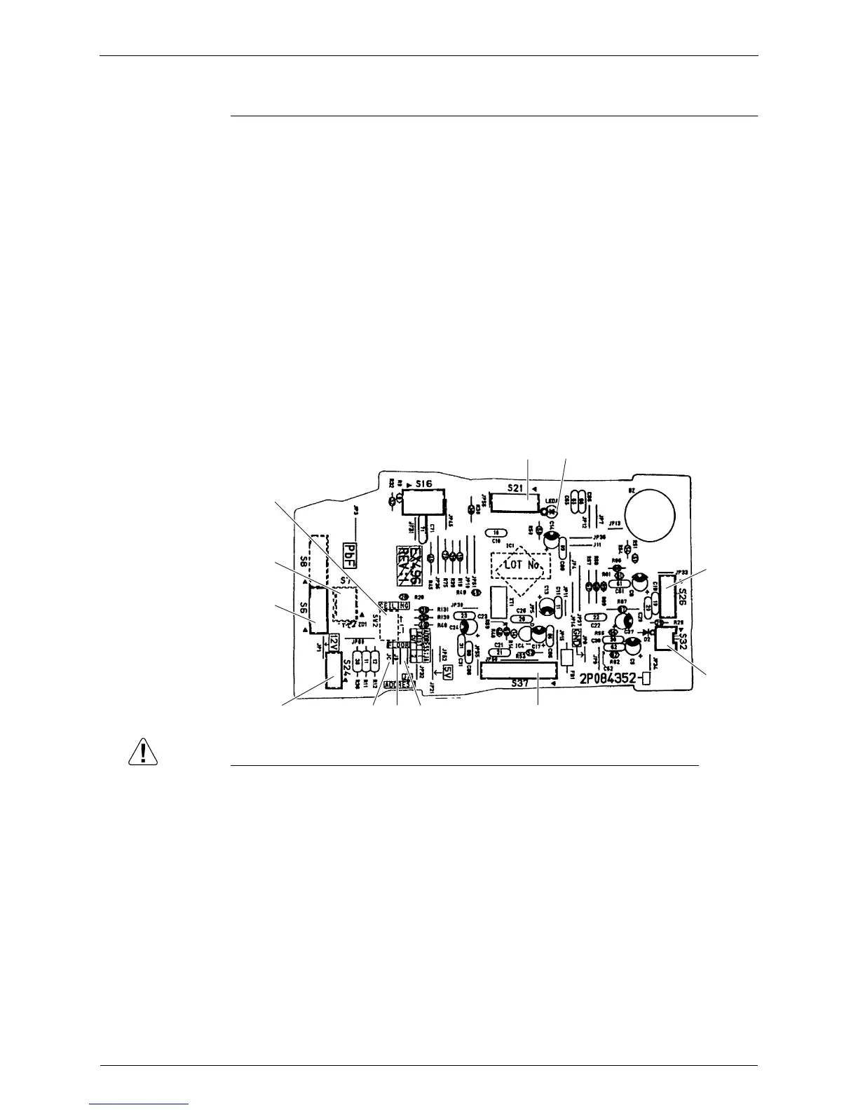
Control PCB
Caution Replace the PCB if you accidentally cut the jumpers other than JA, JB and JC.
Jumpers are necessary for electronic circuit. Improper operation may occur if you cut any of
them.
1) S6 Connector for swing motor (horizontal swing)
2) S7 Connector for AC fan motor
3) S21 Connector for centralized control (HA)
4) S24 Connector for display PCB
5) S26 Connector for signal receiver PCB
6) S32 Connector for indoor heat exchanger thermistor
7) S37 Connector for power supply PCB
8) JA Address setting jumper
∗ Refer to page 226 for detail.
9) JB Fan speed setting when compressor stops for thermostat OFF
JC Power failure recovery function
∗ Refer to page 230 for detail.
10) SW2 Select switch for installation (ceiling or floor)
∗ Refer to page 230 for detail.
11) LED A LED for service monitor (green)
SW2
S7
S6
S24
JC JB JA S37
S32
S26
S21
LED A
2P084352-3
 Loading...