SiBE121123_A Wireless Remote Controller
Printed Circuit Board Connector Wiring Diagram 48
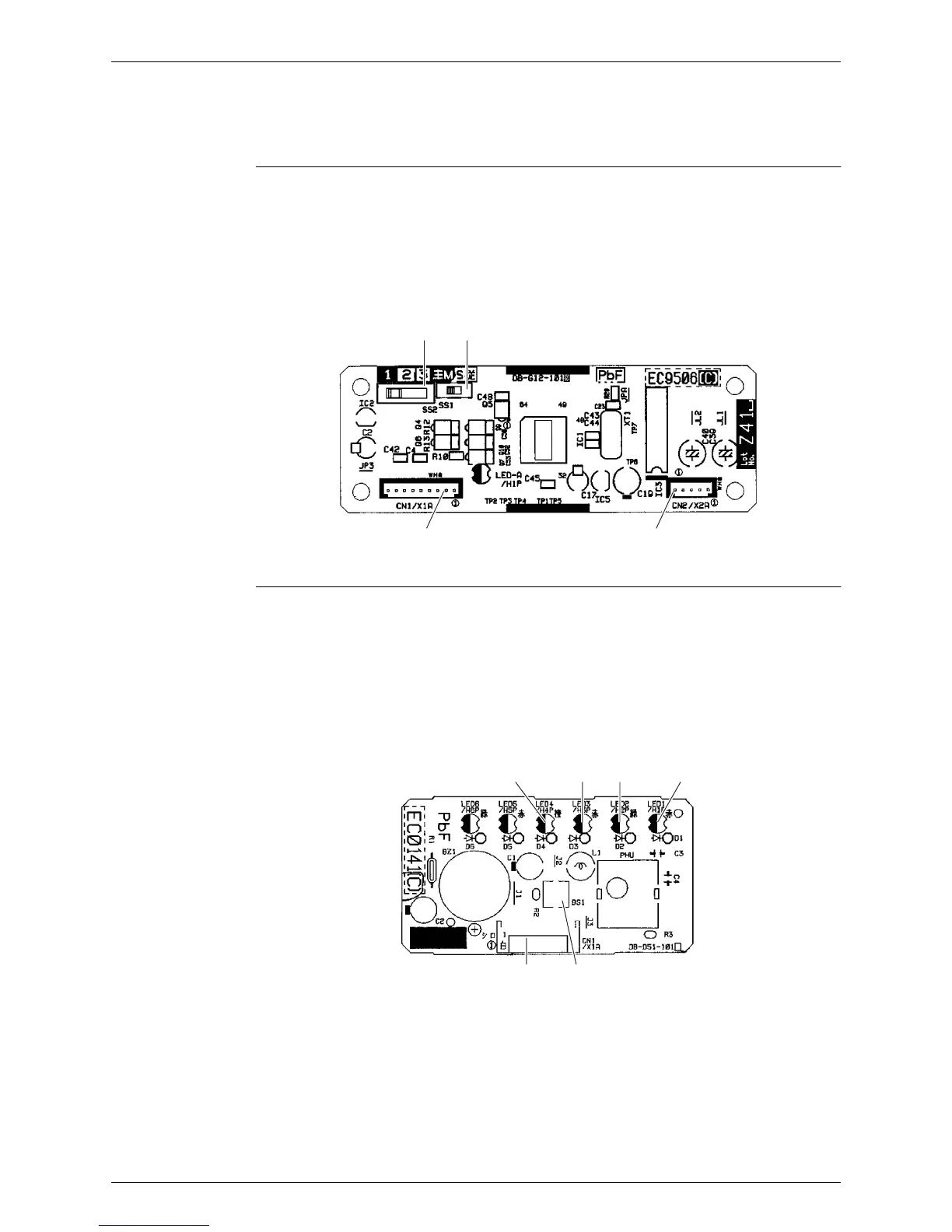
3. Wireless Remote Controller
3.1 BRC7E530W
Signal Receiver
PCB
Display PCB
LED5 and LED6 do not function.
1) X1A Connector for display PCB
2) X2A Connector for control PCB
3) SS1 MAIN / SUB setting switch
SS2 Address setting switch
∗ Refer to page 236 for detail.
3P156326-2
X2A
SS2
SS1
X1A
1) X1A Connector for signal receiver PCB
2) BS1 Forced operation [ON/OFF] button
3) LED1 (H1P) LED for operation (red)
4) LED2 (H2P) LED for timer (green)
5) LED3 (H3P) LED for filter cleaning sign (red)
6) LED4 (H4P) LED for defrost operation (orange)
LED4
X1A
BS1
3P086209-1
LED3 LED2 LED1
 Loading...