SiBE121123_A Check
Service Diagnosis 214
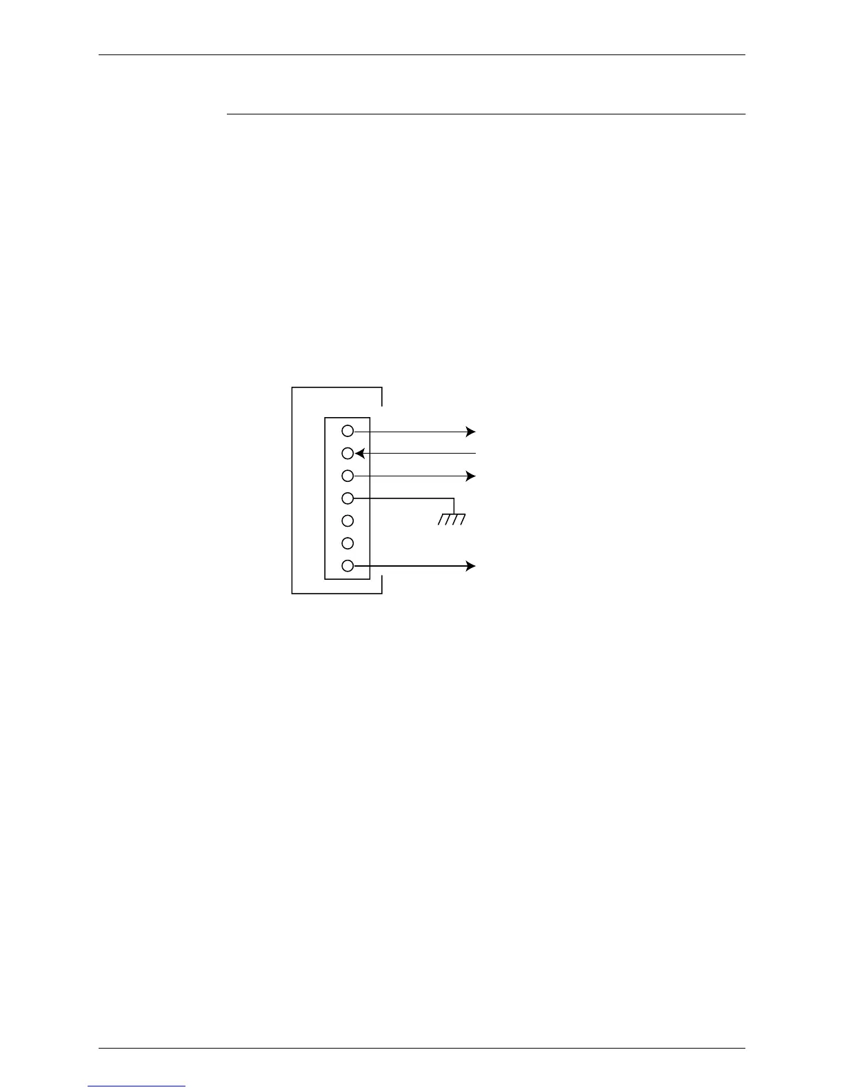
8.10 Rotating Pulse Input on the Outdoor Unit PCB Check
Check No.16 <Outdoor fan motor>
Make sure that the voltage of 320 ± 30 V is applied.
1. Set operation off and power off. Disconnect the connector S70.
2. Check that the voltage between the pins 4 - 7 is 320 VDC.
3. Check that the control voltage between the pins 3 - 4 is 15 VDC.
4. Check that the rotation command voltage between the pins 2 - 4 is 0 ~ 15 VDC.
5. Keep operation off and power off. Connect the connector S70.
6. Check whether 2 pulses (0 ~ 15 VDC) are output at the pins 1 - 4 when the fan motor is
rotated 1 turn by hand.
When the fuse is melted, check the outdoor fan motor for proper function.
If NG in step 2 → Defective PCB → Replace the PCB.
If NG in step 4 → Defective Hall IC → Replace the outdoor fan motor.
If OK in both steps 2 and 4 → Replace the PCB.
1
2
3
4
5
6
7
Actual rotating pulse output (0 ~ 15 VDC)
320 VDC
Rotation command pulse input (0 ~ 15 VDC)
15 VDC
(R10811)
S70
PCB
 Loading...