Home
Daikin
Air Conditioner
2AMX40G3V1B
Daikin 2AMX40G3V1B User Manual
4
of 1
of 1 rating
267 pages
Give review
Manual
Specs
To Next Page
To Next Page
To Previous Page
To Previous Page
Loading...
SiBE12112
3_A
Wired Remote
Controller
Printed Circuit Board
Connector Wiring Diag
ram
46
2.
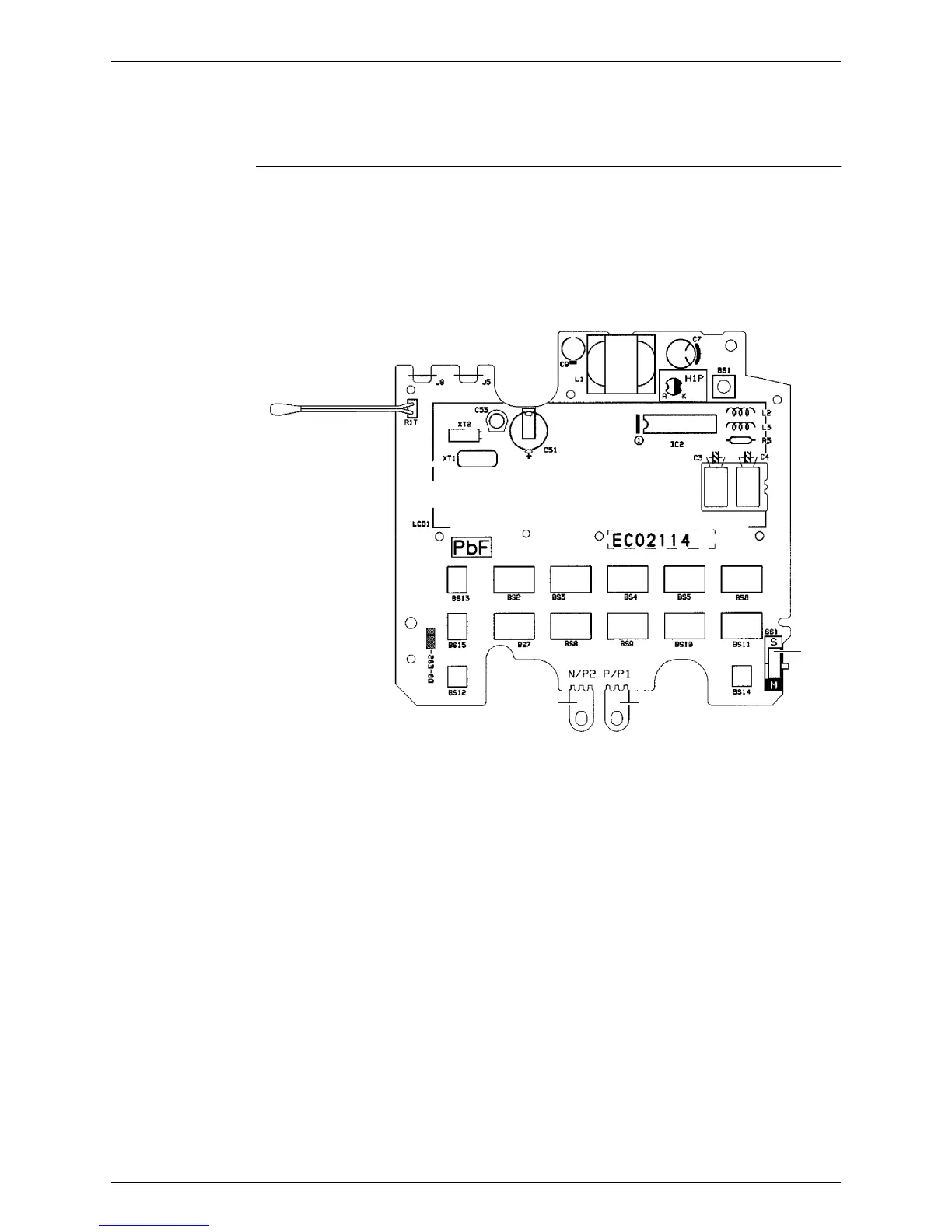
Wired Remote Controller
2.1
BRC
1D52
8
PCB Detail
1)
P1, P2
Terminal for
indoor
unit
2)
R1T
Room
temperature t
hermist
or
3)
SS1
MA
IN / SU
B setting
sw
itch
∗
Refer t
o page 235 for det
ail
.
R1T
P2
P1
SS1
2P113638-2
56
58
Table of Contents
Default Chapter
3
Table of Contents
3
Introduction
7
Safety Cautions
7
Used Icons
11
Part 1 List of Functions
12
Functions
13
Function and Control Part
15
Part 2 Specifications
21
Indoor Unit
22
Specifications
23
Floor Standing Type
33
Duct Connected Type
36
Ceiling Mounted Cassette Type
37
Outdoor Unit
38
Part 3 Printed Circuit Board Connector Wiring Diagram
39
Indoor Unit
40
Ftxg25/35/50Jv1Bw(S)(A)
40
Ctxs15/35K2V1B, Ftxs20/25K2V1B
42
Ftxs35/42/50K2V1B, Ftxs20/25/35/42/50J2V1B, Atxs20/25/35/42/50G2V1B
44
Ftx20/25/35Jv1B, Ftx20/25/35J2V1B, Atx20/25/35Jv1B, Atx20/25/35J2V1B
46
Fvxg25/35/50K2V1B
48
Fvxs25/35/50Fv1B
50
Flxs25/35/50Bavmb
52
Fdxs25/35Eavmb, Fdxs25/35E7Vmb, Fdxs50Cvmb, Fdxs50C7Vmb
54
Ffq25/35/50B8V1B, Ffq25/35/50B9V1B
56
Wired Remote Controller
57
Brc1D528
57
Brc1E51A7
58
Wireless Remote Controller
59
Brc7E530W
59
Outdoor Unit
60
Part 4 Function and Control
62
Function of RA Indoor Unit
63
Temperature Control
63
Frequency Principle
63
Operation Starting Control
65
Airflow Direction Control
66
Fan Speed Control for Indoor Unit
69
RADIANT Operation
71
Program Dry Operation
73
Automatic Operation
74
Thermostat Control
75
NIGHT SET Mode
76
ECONO Operation
77
HOME LEAVE Operation
78
2-Area INTELLIGENT EYE Operation
80
INTELLIGENT EYE Operation
82
Inverter POWERFUL Operation
83
Multi-Colored Indicator Lamp / TIMER Lamp
84
Brightness Setting of Indoor Unit Display
85
Clock Setting
86
WEEKLY TIMER Operation
87
Other Functions
93
Function of SA Indoor Unit
94
Drain Pump Control
94
Remote Controller
95
Thermostat Sensor in Remote Controller
96
Freeze Prevention Control
98
Hot Start Control (in Heating Operation Only)
99
Function of Thermistor
100
Control Specification
102
Mode Hierarchy
102
Frequency Control
103
Controls at Mode Changing / Start-Up
105
Discharge Pipe Temperature Control
106
Input Current Control
107
Freeze-Up Protection Control
107
Heating Peak-Cut Control
108
Outdoor Fan Control
109
Liquid Compression Protection Function
109
Defrost Control
110
Outdoor Electronic Expansion Valve Control
111
Malfunctions
115
Part 5 Remote Controller
117
RA Indoor Unit
118
Ftxg25/35/50Jv1Bw(S)(A), Ctxs15/35K2V1B, Ftxs20/25K2V1B
118
Mode Button
119
Ftxs35/42/50K2V1B
120
Ftxs20/25/35/42/50J2V1B
122
Atxs20/25/35/42/50G2V1B
124
Ftx20/25/35Jv1B, Ftx20/25/35J2V1B, Atx20/25/35Jv1B, Atx20/25/35J2V1B
126
Fvxg25/35/50K2V1B
128
Fvxs25/35/50Fv1B
130
Flxs25/35/50Bavmb
132
Fdxs25/35Eavmb, Fdxs25/35E7Vmb, Fdxs50Cvmb, Fdxs50C7Vmb
134
SA Indoor Unit
136
Brc1D528
136
Brc1E51A7
139
Operation Mode
142
Brc7E530W
144
Part 6 Service Diagnosis
145
Troubleshooting with LED
147
Indoor Unit
147
Outdoor Unit
148
Problem Symptoms and Measures
149
Service Check Function
150
RA Indoor Unit
150
Arc452 Series Remote Controller
153
Arc433 Series Remote Controller
156
SA Indoor Unit
159
Code Indication on Remote Controller
166
RA Indoor Unit
166
SA Indoor Unit
166
Outdoor Unit
167
Troubleshooting for RA Indoor Unit
168
Indoor Unit PCB Abnormality
168
Freeze-Up Protection Control or Heating Peak-Cut Control
170
Fan Motor or Related Abnormality
172
Radiant Panel Temperature Rise, Indoor Electronic Expansion Valve (Motor Operated Valve) Abnormality, Freeze-Up Protection Control (FVXG Series Only)
176
Thermistor or Related Abnormality (RA Indoor Unit)
178
Front Panel Open / Close Fault (FTXG Series Only)
179
Troubleshooting for SA Indoor Unit
180
Indoor Unit PCB Abnormality
180
Drain Level Control System Abnormality
181
Fan Motor (AC Motor) or Related Abnormality
182
Drain System Abnormality
183
Thermistor or Related Abnormality (SA Indoor Unit)
184
Remote Controller Thermistor Abnormality
185
Signal Transmission Error (between Indoor Unit and Remote Controller)
186
Signal Transmission Error (between MAIN Remote Controller and SUB Remote Controller)
187
Field Setting Abnormality
188
Troubleshooting for Outdoor Unit
189
Refrigerant Shortage
189
Low-Voltage Detection or Over-Voltage Detection
191
Outdoor Unit PCB Abnormality or Signal Transmission Error
193
Unspecified Voltage (between Indoor Unit and Outdoor Unit) / Anti-Icing Control in Other Room
196
Anti-Icing Control for Indoor Unit
197
OL Activation (Compressor Overload)
199
Compressor Lock
201
DC Fan Lock
202
Input Overcurrent Detection
203
Discharge Pipe Temperature Control
204
High Pressure Control in Cooling
205
Compressor Sensor System Abnormality
206
Position Sensor Abnormality
207
DC Voltage / Current Sensor Abnormality
209
Thermistor or Related Abnormality (Outdoor Unit)
210
Electrical Box Temperature Rise
212
Radiation Fin Temperature Rise
213
Output Overcurrent Detection
215
Check
217
Thermistor Resistance Check
217
Fan Motor Connector Output Check
218
Hall IC Check
219
Indoor Electronic Expansion Valve Coil Check
219
Power Supply Waveforms Check
220
Outdoor Electronic Expansion Valve Check
221
Four Way Valve Performance Check
222
Inverter Unit Refrigerant System Check
222
Inverter Analyzer Check
223
Rotating Pulse Input on the Outdoor Unit PCB Check
225
Installation Condition Check
226
Discharge Pressure Check
226
Outdoor Unit Fan System Check
227
Main Circuit Short Check
227
Power Module Check
228
Part 7 Trial Operation and Field Settings
229
Pump down Operation
230
Forced Cooling Operation
231
Trial Operation
232
RA Indoor Unit - FTXG, FTXS, ATXS, FTX, ATX, FVXG, FVXS, FLXS, FDXS Series
232
SA Indoor Unit - FFQ Series
234
Field Settings
236
RA Indoor Unit - FTXG, FTXS, ATXS, FTX, ATX, FVXG, FVXS, FLXS, FDXS Series
236
SA Indoor Unit - FFQ Series
242
Outdoor Unit
250
Silicon Grease on Power Transistor / Diode Bridge
251
Part 8 Appendix
252
Piping Diagrams
253
Indoor Unit
253
Outdoor Unit
257
Wiring Diagrams
258
Indoor Unit
258
Outdoor Unit
264
Removal Procedure (Booklet No.)
265
Revision History
266
Other manuals for Daikin 2AMX40G3V1B
Installation Manual
19 pages
Removal Procedure
24 pages
4
Based on 1 rating
Ask a question
Give review
Questions and Answers:
Need help?
Do you have a question about the Daikin 2AMX40G3V1B and is the answer not in the manual?
Ask a question
Daikin 2AMX40G3V1B Specifications
General
Brand
Daikin
Model
2AMX40G3V1B
Category
Air Conditioner
Language
English
Related product manuals
Daikin 2AMXM40M4V1B9
76 pages
Daikin 2AMK40FV1B
29 pages
Daikin R-22
78 pages
Daikin 2MXM50M
114 pages
Daikin 2MXM-N9
76 pages
Daikin 2MXM40M
114 pages
Daikin 2MKS50FV1B
29 pages
Daikin 2MKS40DVMB
230 pages
Daikin 2MXS50FV1B
29 pages
Daikin 2MXS18GVJU
32 pages
Daikin 2MXS50GV1B
341 pages
Daikin 2MXS18NMVJU
282 pages
 Loading...