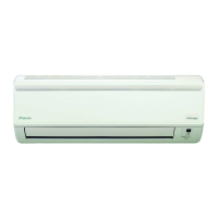
Indoor Unit SiBE041101
11 Printed Circuit Board Connector Wiring Diagram
1. Indoor Unit
Connectors and
Other Parts
PCB (1): Control PCB
PCB (2): Signal Receiver PCB
PCB (3): Display PCB
PCB (4): INTELLIGENT EYE Sensor PCB
1) S1 Connector for DC fan motor
2) S21 Connector for centralized control (HA)
3) S25 Connector for INTELLIGENT EYE sensor PCB
4) S32 Indoor heat exchanger thermistor
5) S41 Connector for swing motors
6) S46 Connector for display PCB
7) S47 Connector for signal receiver PCB
8) H1, H2, H3,
FG
Connector for terminal board
9) JA Address setting jumper
∗ Refer to page 243 for detail.
JB Fan speed setting when compressor stops for thermostat OFF
JC Power failure recovery function (auto-restart)
∗ Refer to page 246 for detail.
10) LED A LED for service monitor (green)
11) FU1 (F1U) Fuse (3.15 A, 250 V)
12) V1 Varistor
1) S48 Connector for control PCB
1) S49 Connector for control PCB
2) SW1 Forced operation ON / OFF button
3) LED1 (H1P) LED for operation (green)
4) LED2 (H2P) LED for timer (yellow)
5) LED3 (H3P) LED for INTELLIGENT EYE (green)
6) RTH1 (R1T) Room temperature thermistor
1) S26 Connector for control PCB
 Loading...