Indoor Unit SiBE121135_A
55 Printed Circuit Board Connector Wiring Diagram
2.5 FVXG25/35/50K2V1B
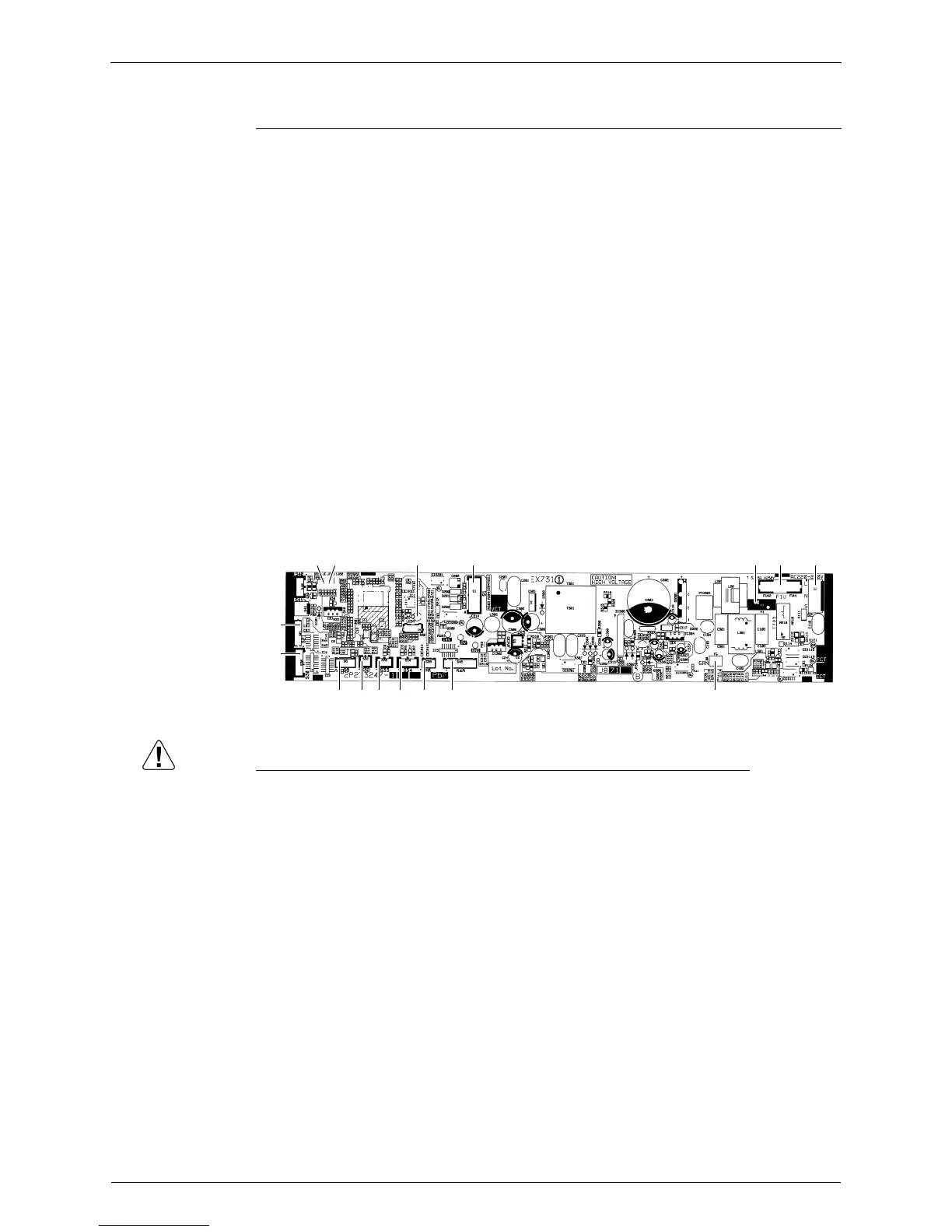
Main PCB
Caution Replace the PCB if you accidentally cut the jumpers other than JB and JC.
Jumpers are necessary for electronic circuit. Improper operation may occur if you cut any of
them.
1) S1 Connector for fan motor
2) S2 Connector for terminal board
3) S6 Connector for swing motor
4) S21 Connector for centralized control (HA)
5) S26 Connector for service PCB
6) S30 Connector for indoor electronic expansion valve coil (motor operated
valve coil)
7) S32 Connector for indoor heat exchanger thermistor
8) S33 Connector for room temperature thermistor
9) S34 Connector for radiant panel thermistors
10)S46 Connector for display PCB
11)FG Connector for earth
12)V1 Varistor
13)JB Fan speed setting when compressor stops for thermostat OFF
JC Power failure recovery function
∗ Refer to page 257 for detail.
14)F1U Fuse (3.15A, 250V)
15)LED A LED for service monitor (green)
S6
S30
S21
S32 S33 S34 S26 S46 FG
LED A S1 V1 F1U S2JBJC
2P273247-1

 Loading...